background image

Electrical and Mechanical Specifications 

• 6HP Eurorack format module 
• 0.98” (25mm) maximum depth 
• 10-pin Eurorack power header 
• Power consumption (maximums):  

• +12V @ 112mA 
• -12V @ 12mA 
• +5V rail not used 

• Audio 

OUT

 jacks 

Frequency Response: 

File:Out = +/-0.1dB max deviation at 20Hz - 20kHz 

21V peak-to-peak = full scale 

Up to +20dB digital gain can be applied while playing using Gain knob 

• Audio 

IN

 jacks 

Signal-to-Noise Ratio (SNR) 

Measurements taken from recordings made in a typical Eurorack case, powered by a 4ms Row 

Power 40 module: 

-91.7dB @ 16-bit, 44.1kHz 

-88.9dB @ 24-bit, 96kHz 

Frequency Response: 

Out:In = max +/-0.1dB from 20Hz to 15kHz. -0.5dB at 20kHz  

20V peak-to-peak maximum before clipping 

Up to +20dB digital gain can be applied while recording or monitoring using 

Gain

 knob 

Record  

 jack 

Incoming trigger starts/stops recording, or starts/re-starts playback 

Trigger voltage must be > 1.6V, rising edge is detected 

microSD card slot accessible from front panel 

Class 10 card included (16GB) 


Jumpers 

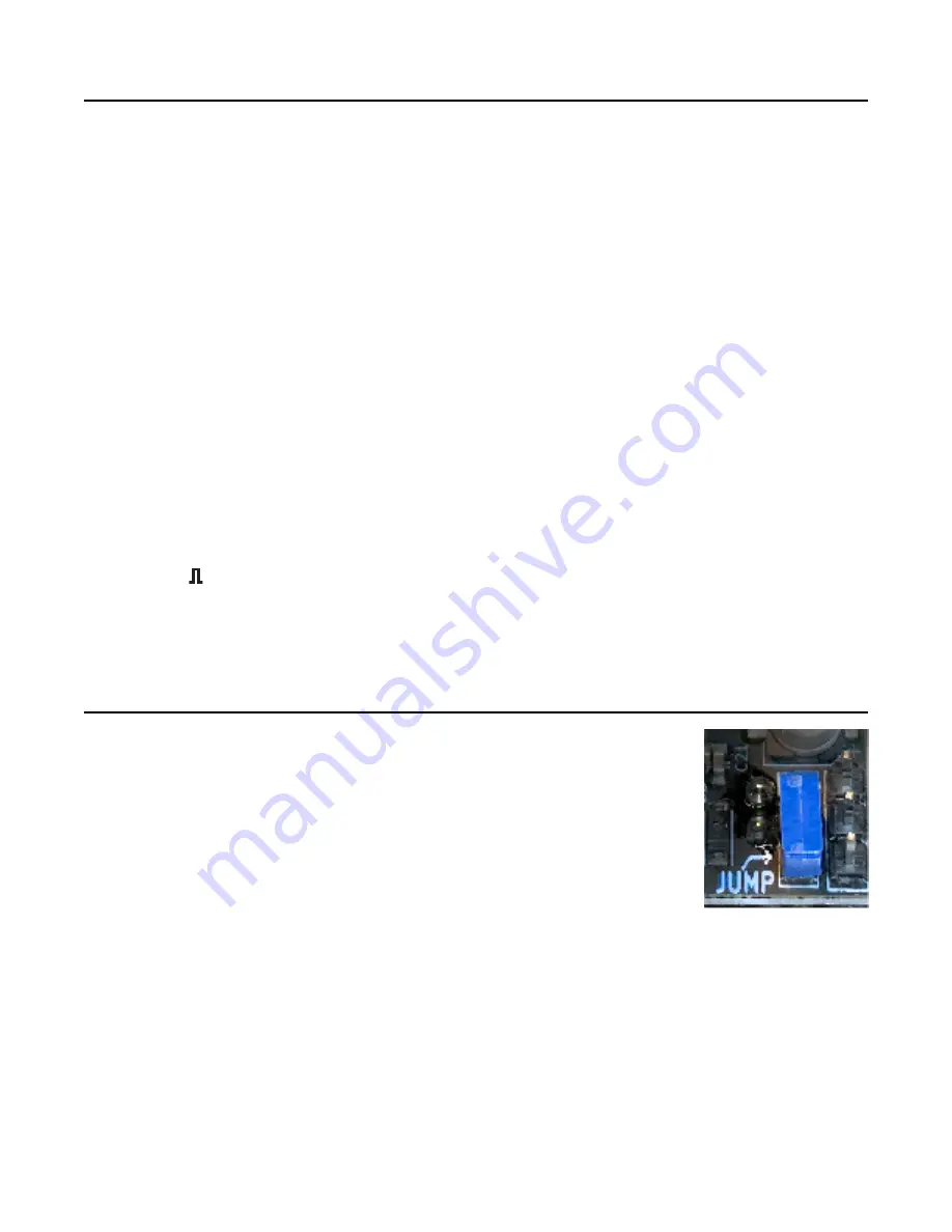
The PCB has one jumper labeled “JUMP”, which fits on a 2-pin header 

located at the bottom right of the PCB. 

The jumper must be installed to enable the normalization of the 

Left IN

 jack to 

the 

Right IN

 jack. If this jumper is missing, patching a signal into the 

Left IN


with nothing plugged into the 

Right IN

 jack will record silence on the right 

channel. 

The jumper should only be removed if you are connecting the 

WAV Recorder


to a 4ms Company Listen module. See the Listen manual for connection 

details.

Page   of 

15

15

Summary of Contents for WAV Recorder

Page 1: ...ystem can be used to browse the folders on the card for playing back wav files A Gain knob allows for up to 20dB of boost and an LED Signal Meter indicates clipping and the signal level Records up to 96kHz 24 bit creating stereo or mono wav files on the microSD card Gain knob and LED level meter make it easy to record a wide range of signal levels Plays standard wav files from the card without ren...

Page 2: ...m on 5 Begin with Tutorial Basic Recording on page 4 of this manual Setting up your WAV Recorder 2 Controls Button Knob Switch and Jacks 3 Tutorial Basic Recording 4 Folders and File Organization 5 Playback 5 Browsing Files for Playback 6 Trigger Jack 7 Pausing Recording 7 Example Patch Multi track Recording 8 Using the WAV Recorder as a Pre amp 9 Busy Light 9 Checking for Free Space 9 Hot Swappin...

Page 3: ... left column represents the left audio channel and the right column represents the right audio channel More lights turned on means there s a louder signal The top red lights indicate clipping If the Signal Meter shows that your signal is either too loud clipping or too quiet you can use the the Gain knob to adjust the level Gain knob The volume level of the signal being recorded or played can be a...

Page 4: ... and press the button The button will turn red and the Busy light will start to flash 6 Record as much as you want and then press the button again Wait for the Busy light to turn off 7 Congratulations You just made a high quality recording The WAV Recorder has now created a wav file on the microSD card You can listen to your recording by flipping the switch to Playback and then pressing the button...

Page 5: ...ack mode any file with any name can be accessed You do not need to rename your files to play them Playback Playing wav files with the WAV Recorder is easy Flip the switch to Playback and press the button The most recent recording will play The button will turn green while a recording is playing Turn the Gain knob to adjust the playback volume You can press the button again to stop playback or it w...

Page 6: ...a bit to indicate there s another page of files before or after it The number of flickers indicates the next or previous page number i e one flicker means you can access the 1st page by turning past that light two flickers means the 2nd page is past that light etc Turn the knob to the first or last light and then keep turning it a little bit more to jump to the next or previous page The light will...

Page 7: ...ve Recording timed loops If you have a rhythmic patch you can feed a slow clock into the trigger jack to record a bar or measure of the patch If you just want to capture just one measure plug in the trigger while the clock gate is low When the clock goes high recording will begin on the start of the measure assuming your clock is synced to the start of the measure When the next measure starts the ...

Page 8: ...icroSD cards onto a computer and combine the files into a multi track file using any audio editing software High precision phase alignment For most purposes the files can be combined simply by snapping the beginnings to the same point However if you are doing some specific work that requires the phase differences between tracks to be exact then you may need to line up the tracks manually In our te...

Page 9: ...ird do a disk repair or first aid using Disk Utility on MacOS or fsck or something similar on Linux After repairing the disk copy all your files off format it in ExFAT and copy your files back on Always keep backups of important files Checking for Free Space You can check the amount of free space on the card by holding the button down for 2 seconds while in Record mode An animation of the lights w...

Page 10: ...evel 0 4dBFS 20Vpp The red LEDs turn bright solid clipping 2 6dBFS 16Vpp The red LEDs turn on dimly 8dBFS 8 5Vpp The white LEDs turn on 12dBFS 5Vpp The upper blue LEDs turn on 21dBFS 1 75Vpp The lower blue LEDs turn on The Signal Meter shows the actual signal present on the output jacks whether you are recording or playing By adjusting the Gain knob while watching the Signal Meter you can set your...

Page 11: ...he left side turn the Gain knob The LEDs in the right column will change when you turn fully to the left 0 fully to the right 100 and or to the center 50 The lights on the right column will tell you the value of the parameter you selected as follows A red light in the left column indicates the Sample Frequency menu its options listed in the right column are 96kHz red 48kHz white or 44 1kHz blue A ...

Page 12: ...mazon or any number of electronics retailers Beware of cheap look alikes and only purchase from a reputable seller Avoid cards with a price under USD 20 they are likely to be fakes The following table reports our findings At 44 1kHz 24bit Stereo on the included Class 10 card a 1 hour recording has a 4 chance of dropping samples Using a faster card is recommended At 48kHz 24bit Stereo or 96kHz 24bi...

Page 13: ...be cleaned up or if it isn t a problem This is just a band aid in case you accidentally record at a higher rate than your card can allow and there s no chance of a re take To avoid the possibility of dropped samples when recording at any rate either use a fast microSD card or keep your settings at a lower rate Checking the Firmware Version When you power on the module the LED Signal Meter will bri...

Page 14: ...rome Turn off any EQ or Bass Boost settings The open source licensed source files in C for compiling with gcc arm can be found at https github com 4ms note as of printing of this manual this is not yet posted microSD Card We include a Class 10 card with the WAV Recorder which is sufficient for recording at 44 1kHz If you need to record at a higher rate use a faster card See Recording Rates section...

Page 15: ...maximum before clipping Up to 20dB digital gain can be applied while recording or monitoring using Gain knob Record jack Incoming trigger starts stops recording or starts re starts playback Trigger voltage must be 1 6V rising edge is detected microSD card slot accessible from front panel Class 10 card included 16GB Jumpers The PCB has one jumper labeled JUMP which fits on a 2 pin header located at...

Reviews: