background image

6

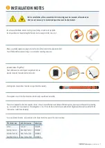
Please note:

 The motor can be installed on the right-hand side as well as on the left-hand side. 

  If the direction of rotation is reversed, please exchange the wires for the up and down direction.

 The setting of the end positions is only possible in the installed state (motor in shutter shaft).

 Never place screws in the area of the tube motor, as they will damage the motor.


Engine damage caused by improper use or unprofessional installation, 

  lead directly to loss of warranty.

 INSTALLATION INSTRUCTIONS

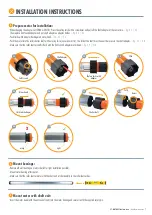
INSTALLATION SHUTTER MOTOR

Installation situation

1

 Counter bearing

*


2

 Ball bearing

*


3

 Roller capsule

*

4

 Shutter shaft

*


5

 Suspension spring

*


6

 Shaft adapter


7

 Tubular motor   

8

 Limit switch adapter


9

 Engine mount

10

 Shutter curtain

*

Accessories; not included

1

 Prepare power connection:

 The mains connection cable of the drive must be laid internally in the empty conduit up to the junction box. 

  The local electrical regulations must be observed.

2

 Remove shutter shaft:

 Lower the roller shutter.

 Open the cover of the roller shutter box and release the suspension springs from the roller shutter shaft.

 Lift roller shutter shaft incl. ball bearing out of the holder.

1 2

3

4

5 6

7

8

9

10

3T-MOTORS Tubular motors

  |  Installation instructions

Summary of Contents for 3T-MOTORS 3T45-E

Page 1: ...0E 3T45 30E 3T45 40E www 3t components de WEEE Reg Nr DE 77028333 INTELLIGENT DRIVES CONTROLS FOR SHUTTERS AND AWNINGS INSTALLATION OPERATING INSTRUCTIONS Instructions and notes for installation and o...

Page 2: ...ge 8 7 Setting the end positions Page 9 Troubleshooting What to do when Page 10 Position of the anti lift devices Page 10 EU Declaration of Conformity Page 11 Hotline 06732 600 0369 3T MOTORS Tubular...

Page 3: ...ulations VDE 0100 part 701 and 702 These drives can be connected in parallel without an isolating relay or central control In this case the max output power of the command transmitter timer or otherwi...

Page 4: ...0 Nm 37 kg 8 m 7 m 190 W 17 U min 3 min 230 V 639 mm 617 mm 2 5 m 4 min IP44 4260336113065 3T45 30E 30 Nm 56 kg 12 m 11 m 240 W 17 U min 3 min 230 V 669 mm 647 mm 2 5 m 4 min IP44 4260336113072 3T45 4...

Page 5: ...motor is designed for short time operation 4 min It has an internal thermal circuit breaker which interrupts the power supply in the event of overheating e g as a result of continuous operation The c...

Page 6: ...SHUTTER MOTOR Installation situation 1 Counter bearing 2 Ball bearing 3 Roller capsule 4 Shutter shaft 5 Suspension spring 6 Shaft adapter 7 Tubular motor 8 Limit switch adapter 9 Engine mount 10 Shut...

Page 7: ...e roller shutter shaft is flush with the limit switch adapter motor head fig 3 9 3 10 4 Mount bearings Remove old wall bearing on motor side left or right installation possible Mount motor bearing at...

Page 8: ...s upstream and downstream leads brown black must be turned Roller capsule Wall bearing Ball bearing Shutter motor 230 V 50 Hz Power grid 230 V 50 Hz 1 brown black L1 Phase 2 blue N Neutral conductor 3...

Page 9: ...against the end stops but stops automatically beforehand Every 60 cycles the drive independently checks and corrects the end positions in fully automatic mode or Manual mode Suspension springs and no...

Page 10: ...ion Swap the two wires for the direction of rotation brown black the motor does not switch off at the set point Check fit of limit switch adapter must be flush with motor head and shutter shaft Roller...

Page 11: ...n Anforderungen der aufgef hrten EG EU Richtlinien erf llt 2014 35 EU Niederspannungsrichtlinie 2014 30 EU EMV Richtlinie 2011 65 EU RoHS Richtlinie 2012 19 EU WEEE Richtlinie angewandte Standards und...

Page 12: ...49 0 6732 600 03 69 Fax 49 0 6732 600 54 30 www 3t components de Opening hours Monday Friday 8 00 17 00 bit ly youtube 3TComponents Social Media Links Info news and tips on roller shutters awnings sma...

Reviews: