


Please refer to user manual for specific configuration
method of logging in to WEB interface and other
configurations about network management function.
【
Specification
】
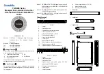
Panel
100M M12
10/100Base-T(X), M12
(Female), 4-Pin D-Coded,
automatic flow control, full/half
duplex mode, MDI/MDI-X
automatic detection
Gigabit M12
10/100/1000Base-T(X)
,
M12(Female)
,
8-Pin
A-Coded/X-Coded automatic
flow control, full/half duplex
mode, MDI/MDI-X automatic
detection; support Bypass
function
Console port
CLI command management
port, RJ45
Alarm interface
Model
I
:3-Pin 5.08mm pitch
terminal blocks,
Model II,model III:7-Pin female
M23 portSupport 1 relay alarm
output, the current loading
capability is 5A@30VDC or
10A@125VAC
Indicator
Power indicator, run indicator,
interface
indicator,
alarm
indicator
Exchange attributes
Backplane bandwidth
128G
Packet buffer size
12Mbit
MAC table size
16K
Power supply
Model I
power
supply
:110VAC/DC
(100~240VAC/DC)
input terminal: 3-Pin 5.08mm
pitch terminal blocks
Model II
power
supply:
110VAC/DC
(dual)
input terminal: 7-Pin female M23
port
Model III
Power supply: 24VDC(dual)
Input terminal: 7-Pin female
M23 port
Consumption
Model I
No-load
Full-load : 14.85W@110VDC
Model II
No-load
Full-load : 17.9W@110VDC
Model III
No-load
Full-load :16.3W@24VDC
Working environment
Model I
Working temperature : -40
~
75
℃
Storage temperature : -40
~
75
℃
Working humidity : 5%
~
95%(no
condensation)
Protection grade : IP40 (metal
shell)
Model II Model III
Working temperature : -40
~
75
℃
Storage temperature : -40
~
85
℃
Working humidity : 5%
~
95%(no
condensation)
Protection grade :IP40 (metal
shell)


