


2
D0- (DA-)
The first group of bi-directional data
of Gigabit Ethernet negative
3
D1+ (DB+)
The second group of bi-directional
data of Gigabit Ethernet positive
4
D1- (DB-)
The second group of bi-directional
data of Gigabit Ethernet negative
5
D3+ (DD+)
The fourth group of bi-directional
data of Gigabit Ethernet positive
6
D3- (DD-)
The fourth group of bi-directional
data of Gigabit Ethernet negative
7
D2- (DC-)
The third group of bi-directional data
of Gigabit Ethernet negative
8
D2+ (DC+)
The third group of bi-directional data
of Gigabit Ethernet positive
Model
II
Model
III
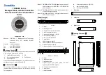
provide
20
10/100/1000Base-T(X) interfaces. The
interface type is M12 X-Coded 8-Pin slot
(female) and its pin definitions are as
follows:
No.
Definition
Description
1
BI + (DA+)
The first group of bi-directional data
of Gigabit Ethernet positive
2
BI - (DA-)
The first group of bi-directional data
of Gigabit Ethernet negative
3
BI + (DB+)
The second group of bi-directional
data of Gigabit Ethernet positive
4
BI - (DB-)
The second group of bi-directional
data of Gigabit Ethernet negative
5
BI + (DD+)
The fourth group of bi-directional
data of Gigabit Ethernet positive
6
BI - (DD-)
The fourth group of bi-directional
data of Gigabit Ethernet negative
7
BI - (DC-)
The third group of bi-directional data
of Gigabit Ethernet negative
8
BI + (DC+)
The third group of bi-directional data
of Gigabit Ethernet positive
Console Port Connection
This device provides 1 program debugging port based on
RS232, which could be connected to PC for device CLI
command management. The interface adopts RJ45 port. The
pin definitions of RJ45 are as follows:
No.
2
3
5
Definition
TXD
RXD
GND
【
Restoring Factory Settings
】
The steps of restoring factory settings of Model II Model III are
as follows: press and hold restore factory setting button to
power on the device again. Release the button after 3-4s to
finish restoring factory settings.
【
Checking LED Indicator
】
This device provides LED indicators for monitoring the work
status of the device, which has simplified the troubleshooting
process comprehensively. The function of each LED is
described in the table as below:
LED
Status
Description
PWR
ON
PWR is connected and running
normally
OFF
PWR is disconnected and running
abnormally.
ALARM
ON
Power supply, port link alarm
OFF
Power supply, port link without
alarm
RUN
ON
The device is powered on or the
device is abnormal.
OFF
The device is powered off or the
device is abnormal.
Blinking
Blink 1 time/s, system is running
well.
Link/Act
ON
Ethernet port connection is active.
Blinking
Data transmitted
OFF
Ethernet port connection is inactive.
【
Logging in to WEB Interface
】
This device supports WEB management and configuration.
Computer can access the device via Ethernet interface. The
way of logging in to device
’s configuration interface via IE
browser is shown as below:
Step 1
Configure the IP addresses of computer and the
device to the same network segment, and the
network between them can be mutually accessed.
Step 2
Enter device
’s IP address in the address bar of the
computer browser.
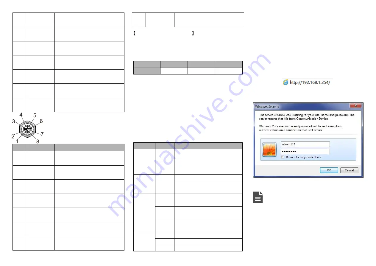
Step 3
Enter device
’s username and password in the login
window as shown below.
Step 4
Click
“OK” button to login to the WEB interface of
the device.
Note:
The default IP address of the device is “192.168.1.254”.
The default username and password of the device is
“admin123”.
If the username or password is lost, user can restore it to
factory settings via device DIP switch or management
software; all modified configurations will be cleared
after restoring to factory settings, so please backup
configuration file in advance.


