background image

3M

 Multimedia Projector MP8670/8745/8755/8770

Adjustments

Copyright 

 2000, 3M IPC.  All Rights Reserved.

1-23

23

24

22

14

30

29

16

28

31

17

32

33

15

25

27

26

20

12

13

21

11

19

18

10

6

4

8

2

1

3

7

5

9

V/6

V/3

V/3

V/6

H/6

H/6

H/3

H/3

23

24

22

14

30

29

16

28

31

17

32

33

15

25

27

26

20

12

13

21

11

19

18

10

6

4

8

2

1

3

7

5

9

V/6

V/3

V/3

V/6

H/6

H/6

H/3

H/3

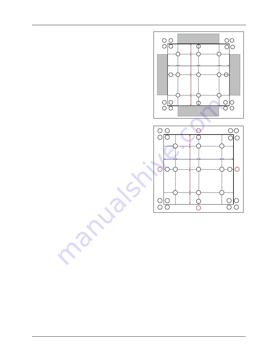
14.


The next adjustments will be to balance the color
uniformity shown in gray at right.  The following are
visual color uniformity checks and adjustments for
color uniformity of the periphery.

15.


Adjust 

points 18 through 21

 to achieve color

uniformity.

Summary of Contents for MP8670l

Page 1: ...INCLUDING BUT NOT LIMITED TO ANY IMPLIED WARRANTY OF MERCHANTABILITY OR FITNESS FOR A PARTICULAR PURPOSE If this product is defective within the warranty period stated above your exclusive remedy sha...

Page 2: ...Checkpoints 3 1 3 2 Power Cannot be Turned on Flowchart 3 2 3 3 Lamp Does Not Light Flowchart 3 3 3 4 No Picture RGB Only Flowchart 3 5 3 5 No Picture Video Only RGB Good Flowchart 3 6 3 6 No Picture...

Page 3: ...e made and specific tools needed to complete each adjustment 1 2 Section Contents Machine Identification Technician Tools Cleaning LCD Panels Convergence White Balance Sample Hold Timing MP8670 8745 V...

Page 4: ...used for all advanced adjustment procedures Use for white balance adjustments 1 4 2 Chroma Meter 3M recommends the Minolta CL100 Chroma Meter or equivalent Use for white balance adjustments 1 4 3 Phil...

Page 5: ...emove any dust from the outside of the projection lens with a lint free cloth If dust remains on the projection image the LCD s and the air filter need to be cleaned 5 The cleaning procedure that foll...

Page 6: ...3 The voltage settings for each input color need to be programmed into the video test generator Refer to the video test generator user s guide for further assistance 4 Turn on the MP8670 8745 and all...

Page 7: ...or equivalent MP8670 OR Input the XGA VESA 60 cross hatch timing signal or equivalent MP8745 2 Select red and green and check convergence 3 Select blue and green and check convergence 4 Select all th...

Page 8: ...ite balance adjustment 1 Check the convergence prior to adjusting the white balance Refer to the previous section for procedure 2 Turn on the projector and allow it to run for 10 minutes This warms up...

Page 9: ...to display the Test Menu 3 The Menu at the right will appear 4 Under Video the following choices appear SECAM R Y SECAM B Y VI BRIGHT VI CONTRAST 5 Under C UNIF the following will appear This function...

Page 10: ...3M Multimedia Projector MP8670 8745 8755 8770 Adjustments Copyright 2000 3M IPC All Rights Reserved 1 8 7 Under S H the following will appear 8 Under SPECIAL the following will appear...

Page 11: ...ttern so it is most clearly visible 3 Reset S H Position the cursor on S H in the adjustment Menu and Press the RESET key Adjustment Procedure 1 Use S H S H Timing in the Adjustment Menu until the Ver...

Page 12: ...or XGA MP8745 VESA 60 timing signal to input a 0 7V p p cross hatch signal 3 Press the AUTO button on the Remote Controller Adjustment Procedure 1 Use the SVGA MP8670 or XGA MP8745 VESA 60 timing sig...

Page 13: ...1 Make this adjustment after completing SUB H POSI 2 Use a SVGA MP8670 or XGA MP8745 VESA 60 timing signal to input a 0 7V p p cross hatch signal 3 Use H PHASE in the Adjustment Menu to adjust the cro...

Page 14: ...M Multimedia Projector MP8670 8745 8755 8770 Adjustments Copyright 2000 3M IPC All Rights Reserved 1 12 6 Display Ghost Test Pattern 7 Use S H GHOST G to adjust so that the Green Ghost is at a minimum...

Page 15: ...3M Multimedia Projector MP8670 8745 8755 8770 Adjustments Copyright 2000 3M IPC All Rights Reserved 1 13 8 Display Ghost Test Pattern 9 Use S H GHOST B to adjust so that the Blue Ghost is at a minimum...

Page 16: ...XGA MP8745 VESA 60 timing sugnal to input a 0 35V p p R primary color Signal for every other line 3 Use DAC P V COM R from the adjustment Menu to adjust Flicker to a minimum 4 Use a SVGA MP8670 or XGA...

Page 17: ...8745 8755 8770 Adjustments Copyright 2000 3M IPC All Rights Reserved 1 15 60 timing signal to input a 0 35V p p B primary color Signal for every other line 7 Use DAC P V COM B from the adjustment Menu...

Page 18: ...s adjustment after completing Flicker Adjustment 2 Use an SVGA MP8670 or XGA MP8745 VESA 60 timing signal to input a 0 7 V p p 16 step Gray Scale 3 Use DAC P NRSH in the adjustment menu to adjust unti...

Page 19: ...G at 30 Lock DAC P BLACK2 GAIN G at 50 Use DAC P SUB BRIGHT G to adjust the last two of the 16 steps on the bright side so they can no longer be distinguished then come back slightly After adjusting i...

Page 20: ...es in the center of the screen to the following X 0 280 0 005 Y 0 345 0 01 Medium brightness white level 7 Repeat steps 4through 7 as necessary to check and readjust low and medium level brightness wh...

Page 21: ...3 1 7 10 Color Uniformity Adjustment Adjustment Preparations 1 Make this adjustment after completing the White Balance Adjustment 2 This adjustment is to assure color uniformity over the entire scree...

Page 22: ...y color signal 50 Green 2 Measure the illumination at points No 2 and No 3 The Values should be No 2 Y2 lux No 3 Y3 lux 3 Determine which point No 2 or No 3 has the higher illumination 4 Adjust the hi...

Page 23: ...0 6 4 8 2 1 3 7 5 9 V 6 V 3 V 3 V 6 H 6 H 6 H 3 H 3 23 24 22 14 30 29 16 28 31 17 32 33 15 25 27 26 20 12 13 21 11 19 18 10 6 4 8 2 1 3 7 5 9 V 6 V 3 V 3 V 6 H 6 H 6 H 3 H 3 7 The next adjustments wil...

Page 24: ...H 6 H 6 H 3 H 3 23 24 22 14 30 29 16 28 31 17 32 33 15 25 27 26 20 12 13 21 11 19 18 10 6 4 8 2 1 3 7 5 9 V 6 V 3 V 3 V 6 H 6 H 6 H 3 H 3 10 The next adjustments will be to balance the color uniformi...

Page 25: ...V 3 V 3 V 6 H 6 H 6 H 3 H 3 23 24 22 14 30 29 16 28 31 17 32 33 15 25 27 26 20 12 13 21 11 19 18 10 6 4 8 2 1 3 7 5 9 V 6 V 3 V 3 V 6 H 6 H 6 H 3 H 3 14 The next adjustments will be to balance the col...

Page 26: ...H 6 H 6 H 3 H 3 23 24 22 14 30 29 16 28 31 17 32 33 15 25 27 26 20 12 13 21 11 19 18 10 6 4 8 2 1 3 7 5 9 V 6 V 3 V 3 V 6 H 6 H 6 H 3 H 3 16 The next adjustments will be to balance the color uniformi...

Page 27: ...ectrical shocks unplug projector power cord before performing any maintenance to electrical components To avoid burns to fingers allow projector lamp and internal projector components to cool off prio...

Page 28: ...to cool off prior to lamp removal or disassembly Remove the top cover to access the internal projector components 1 Remove one 1 screw on back of projector Note If equipped remove three 3 screws secur...

Page 29: ...0 Disassembly Reassembly Copyright 2000 3M IPC All Rights Reserved 2 3 7 6 6 Carefully lift front of top cover to the open position 7 Remove ribbon cable at circuit board and release wire from plastic...

Page 30: ...assembly 9 Remove six 6 cable wire connectors 10 Remove five 5 cable wire connectors Note Some of these wire connectors are on the underside of the circuit board 11 Remove one 1 ground wire screw 12 R...

Page 31: ...ming any maintenance to electrical components To avoid burns to fingers allow projector lamp and internal projector components to cool off prior to lamp removal or disassembly Remove top cover and mai...

Page 32: ...urns to fingers allow projector lamp and internal projector components to cool off prior to lamp removal or disassembly Remove top cover and main PWB board 1 Release three 3 ribbon connectors Note Sli...

Page 33: ...nd internal projector components to cool off prior to lamp removal or disassembly Remove top cover main PWB board and driver PWB board 1 Remove four 4 silver screws securing RGB input board to side of...

Page 34: ...electrical components To avoid burns to fingers allow projector lamp and internal projector components to cool off prior to lamp removal or disassembly Remove top cover main board drive board ballast...

Page 35: ...llow projector lamp and internal projector components to cool off prior to lamp removal or disassembly Remove top cover main board drive board ballast and DC power fan 1 Remove two 2 screws securing f...

Page 36: ...lectrical components To avoid burns to fingers allow projector lamp and internal projector components to cool off prior to lamp removal or disassembly 1 Remove two 2 screws securing bottom of ballast...

Page 37: ...tenance to electrical components To avoid burns to fingers allow projector lamp and internal projector components to cool off prior to lamp removal or disassembly Remove top cover main board drive boa...

Page 38: ...intenance to electrical components To avoid burns to fingers allow projector lamp and internal projector components to cool off prior to lamp removal or disassembly Remove top cover and main PWB board...

Page 39: ...ug projector power cord before performing any maintenance to electrical components To avoid burns to fingers allow projector lamp and internal projector components to cool off prior to lamp removal or...

Page 40: ...ght 2000 3M IPC All Rights Reserved 3 1 3 Troubleshooting This section provides flowcharts to aid in troubleshooting the 3M MP8670 8745 Multimedia Projector 3 1 Troubleshooting Checkpoints The followi...

Page 41: ...n the Main PWB at Standby Mode Measure Voltage at Pin 28 of EDI1 on the Main PWB at Standby Mode Power Unit Circuit Fuse Filter PWB Disconnect ETEP from Main PWB Retry Turn On Main PWB Temperature PWB...

Page 42: ...uit Short between Pin 1 and 2 of ELC1 on the Main PWB and Try again Measure Voltage at the CHK0082 EDS1 on the Main PWB Standby Mode Set the Lamp Cover LIMIT SWITCH LAMP DOOR What is the State of LAMP...

Page 43: ...P Indicator Is Pin 1 of EBAR on the Main PWB set to H Main PWB No Power Unit Ballast Yes H 5V Retry after Shorting between Pin 1 and 3 of EBAF on the Main PWB and Retry Short between Pin 1 and 3 of EI...

Page 44: ...Is the 1 2 Selected Signal Changed at pin 43 CHK007 of EDI1 on the Main PWB Yes L RGB1 H RGB2 H 5V Main PWB No RGB Input Terminal PWB No Are Signals Input at each Pin of EDI1 on the Main PWB Yes Main...

Page 45: ...l Yes 6 9V Are the Input Signals Output at Pins 1 3 5 of EVSI on the Main PWB VIDEO Input Terminal VIDEO Input Terminal PWB No Yes Input Both S Signal Composite Video Signal 49 CHK002 VIDEO R signal 4...

Page 46: ...K075 H sync 63 CHK074 V sync 15 66 CHK055 CLK Are Signals Input at the Pins below of EMD1 on the Main PWB No Main PWB Yes Drive PWB No PWB Input Terminal RGB PWB Signal 4 CHK0041 6 6V 6 CHK0043 17 0V...

Page 47: ...gnal Output at Pins 8 10 of EVS1 on the Main PWB VIDEO Input Terminal No PWB Input Terminal VIDEO Yes Power Unit Circuit Signal PWB 8 Audio L 10 Audio R Check at operating mode RGB and VIDEO Input Sig...

Page 48: ...RS232C PS 2 ADB Serial 1 2 CLK 3 DATA DATA 6 SEL0 SEL0 SEL0 SEL0 7 RTS RTS RTS RTS 9 5v 5v 10 GND GND GND GND 12 SEL1 SEL1 SEL1 SEL1 13 RDP 14 TDP TD Check at operating mode Cannot Control Mouse or R...

Page 49: ...8755 8770 Troubleshooting Copyright 2000 3M IPC All Rights Reserved 3 10 3 9 Can Not Control USB Mouse Can Not Control USB Mouse Is the Voltage at Pin 26 CHK0019 of EDI1 on the Main PWB set to H No M...

Page 50: ...3 10 Signal Waveforms of P501 P601 and P701 Input Signal is VGA3 7 5V DC 4V 9V 1H 1 8 pin 5 PCG pin 1 36 V COM 4V 9V 2H V DATA 4V 9V 1H 12 5V 1H pin 8 VCP pin 9 VCP 4V 9V 200nS 1H HMC EG01 14 5V ER01...

Page 51: ...edia Projector MP8670 8745 8755 8770 Troubleshooting Copyright 2000 3M IPC All Rights Reserved 3 12 Signal Waveforms of P501 P601 and P701 Input Signal is VGA3 Continued pin 30 31 SIG 1 2 7 5V 4 5V 4...

Page 52: ...ton on the top of the projector or the Video1 2 button on the remote control Signal Board The video signal passes though the video signal selector then to the comb filter where it is split into the ch...

Page 53: ...rved 4 2 Driver Board Refer to driver board information for video RGB Out RGB out simply takes the information in its analog state and passes it through an amplifier to the terminal out Additional ele...

Page 54: ...has its own measurable wavelength or combination of wavelengths The wavelengths of light are not colored but produce the sensation of color 4 2 2 Electromagnetic Spectrum All wavelengths of light are...

Page 55: ...hemselves allowing the light to pass through the pixels Shades of gray are obtained by inputting voltages that fall between full off no voltage and full on full voltage The cells are refreshed at the...

Page 56: ...a DC 260 watt metal halide bulb is capable of producing 550 lumens of uniform brightness across the entire projection image The metal halide bulbs should never be touched When oil from your skin touc...

Page 57: ...ave plate polarizer that allows for passage of both horizontal and vertical light waves mirrors dichroic mirrors polarizers and LCD panels Component Description Lamp Projects light Mirror Reflects all...

Page 58: ...3M Multimedia Projector MP8670 8745 8755 8770 Theory and Diagrams Copyright 2000 3M IPC All Rights Reserved 4 7 4 6 Block Diagram...

Page 59: ...4 7 Wire Diagrams Copyright 2000 3M IPC All Rights Reserved 4 8 4...

Page 60: ...4 7 Wire Diagrams Copyright 2000 3M IPC All Rights Reserved 4 9...

Reviews: