3e–525C–2 Wireless Access Point
Chapter 2: Hardware Installation
16
29000155-001 A
3e–525C–2 Wireless Access Point
Chapter 2: Hardware Installation
29000155-001 A
17
Antenna Installation
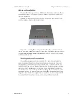
The 3e–525C–2 ships with two 5dBi omni-directional antennas. These
antennas should be connected to the AP antenna connectors located on
the rear of the unit.
NOTE
: Make sure a lightning arrestor is installed between the unit
and the antenna. See the previous section.
If you are not using the access point function then you do not need
the AP antennas. Make sure during your configuration set up that you go
to the
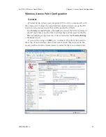
Wireless Access Point—General
screen and set the Tx Pwr Mode
to Off (see Chapter 3).
Sealing Antenna Connections
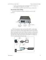
Once all antennas have been installed, the connections should be
sealed to protect them from the exterior harsh environment. Use a self
amalgamating polyisobutylene tape which, over a period of hours, ad-
heres to itself and forms a single amalgamated rubber molding conform-
ing to the shape of the item it is covering. Once the tape is in place for
several hours, it forms a shaped rubber molding that is resistant to water
and most solvents. It remains stable over a wide temperature range and
degrades very slowly in sunlight. If you need to remove the tape after it
has sealed for 30 minutes or more, cut it away with a sharp knife.
Summary of Contents for AirGuard 3e-525C-2
Page 2: ...This page intentionally left blank ...
Page 3: ...3e Technologies International s AirGuard Wireless Access Point User s Guide Model 3e 525C 2 ...
Page 8: ...vi 29000155 0001 A This page intentionally left blank ...
Page 76: ...3e 525C 2 Wireless Access Point Chapter 4 Wireless Bridge Configuration 68 29000155 001 A ...

