3DPlatform.com
8
Initial Printer Setup
USB Connection
Locate the USB cord on the front of the printer. Plug the
USB cord into your computer.
Note:
It is recommended to install the driver and 3D printing software
PRIOR to connecting the printer to your computer.
Launch your 3D printing software and connect to the 3DP
Workbench printer. You may need to 'Refresh Ports' in
order for your computer to initially find the printer.
Sensor Verification
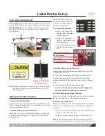
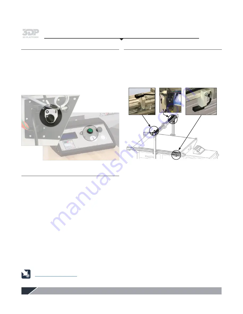
The 3DP Workbench printer has three position sensors–
one for the X axis, one for the Y axis, and one for the
Z axis. These sensors prevent the extruder and/or the
actuators from traveling beyond the designated print
area which can cause serious damage or breakage to the
extruder, glass, and/or the mechanical hardware on the
printer.
Important:
Each 3DP Workbench printer is tested and
calibrated prior to shipping, but it is important to verify
the functionality of the sensors in case of damage or
movement during the shipping process.
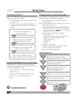
• Hold a piece of metal–such as a coin–under each
sensor location. The red light indicates the sensor is
operational.
• Contact 3D Platform if sensors are non-operational.
Do not attempt
to operate printer.
Visit www.3DPlatform.com
Powering up
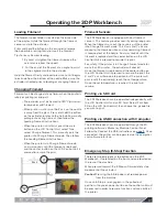
1. Turn on the power switch located on the base unit.
2. Press the green power button on the control unit.
The power outlet on the base unit is located toward the
right, rear side. The control unit is located on the work
area toward the front of the printer.
In case of emergency, press one of the Emergency Stop
buttons (located on the front and rear of the machine).
1. Connect a PC that is running Simplify3D (or other host
program of customer’s choice).
2. Locate each of the end stop sensors on the machine,
3. Verify that the machine is not in the home position.
This means that none of the end stop sensors should
be triggered.
4. From the communication area of the 3D printer host
program that the customer has chosen to use type
“M119”.
– Verify that the response displayed after the M119
command shows that each of the end stop sensors
(X,Y,Z) display “Open”.
5. Cover the sensing area (marked by a target on the
sensor) with a piece of metal. This will ‘activate’ the
sensor.
6. From the communication area of the 3D printer host
program that the customer has chosen to use type
“M119”.
– Verify that the response displayed after the M119
command shows that the sensor that the customer
has covered now displays “Open and Active”.
7. Repeat steps 5 and 6 for the other two end stop
sensors.
The LED on the sensor itself will only show that the
sensor has power. It does not show whether a signal is
being sent or not.
1.
2.

