page
58
of
62
3DGence DOUBLE P255 | version 09.2018
6.
Mount the top enclosure part, so that extruders are placed in the cutout of the part (fig. 70). Top enclosure part should
lay on the rear enclousure part. Magnets will hold the element in place.
Fig. 70 Mounting the top enclosure part
7.
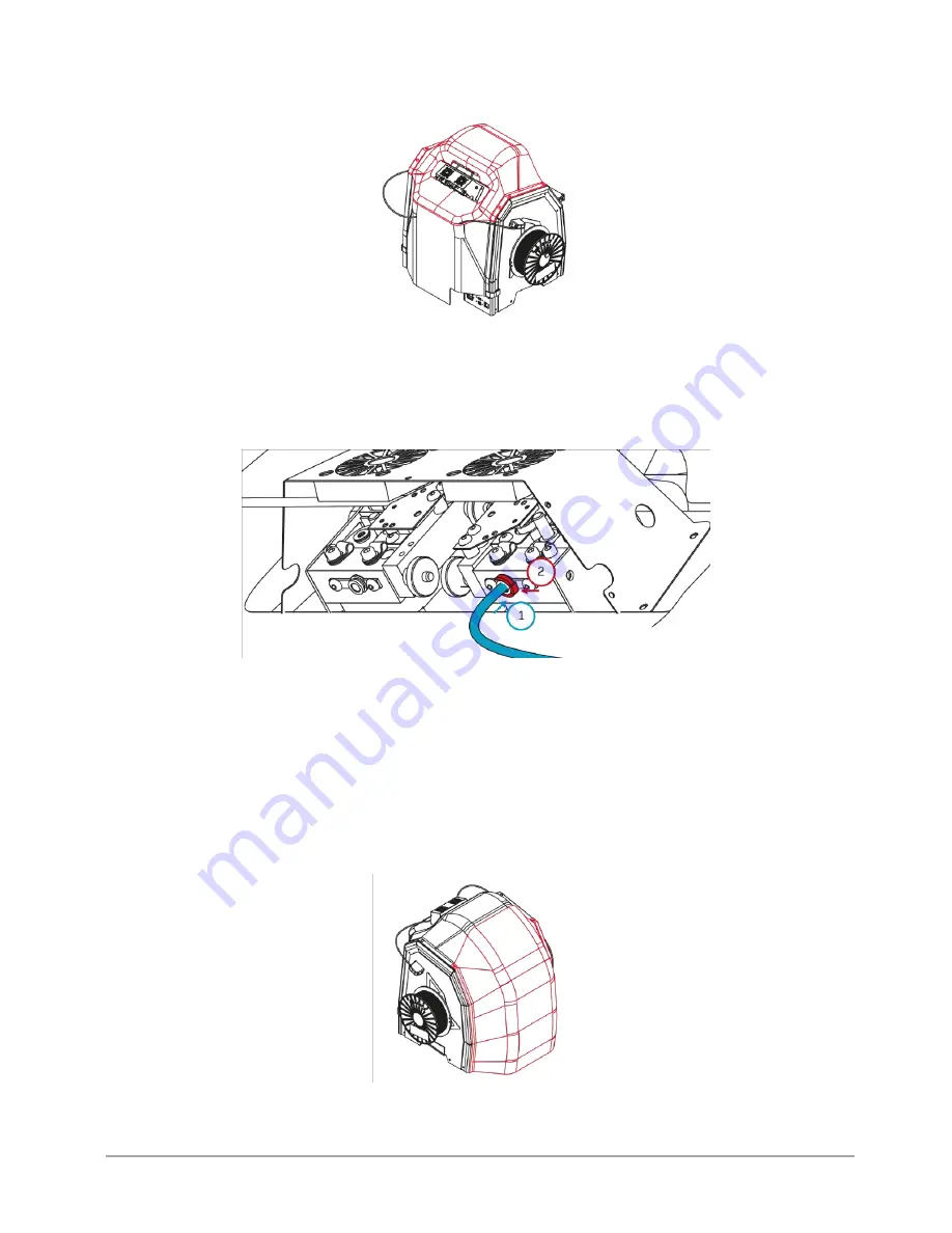
Plug in the bowden tubes to the T0 and T1 extruders (fig. 71). To do that:
•
plug in bowden tube into the nipple (fig. 71, step 1). Make sure that bodwen tube is pushed to the end (about 2 cm,
until resistance is felt),
•
put the collect clip on (fig. 71, step 2).
Fig. 71 Plugging in the bowden tubes to the T0 and T1 extruders
WARNING:
mounting the front enclosure part in the next step of this manual will prevent access to the control panel. If you
are planning to print, first:
•
turn the printer on,
•
load the materials by choosing:
MATERIALS → LOAD MODEL MATERIAL/LOAD
SUPPORT MATERIAL
and follow the steps
on the screen,
•
start printing by choosing the file from the list and pressing PRINT.
8.
Mount the front enclosure part. Front part should overlap the top enclosure part (fig. 72). Magnets will hold the enclosure
assembly together.
Fig. 72 Mounting the front enclosure part


