background image


4-2


Figure 4-2 

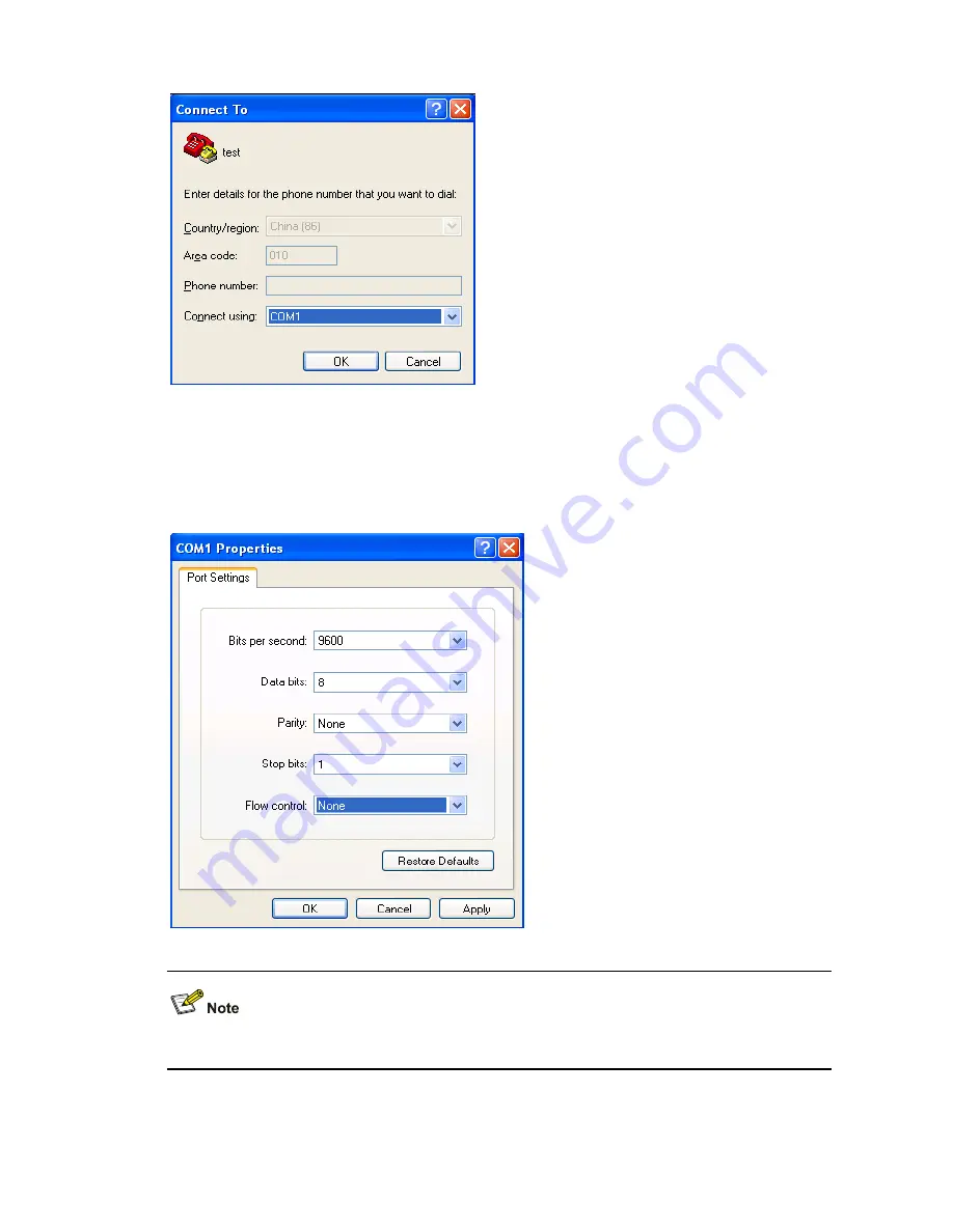
Select the serial interface used for HyperTerminal connection 


4) Click 

OK

 and the system displays the following interface, as shown in Figure 4-3. On the interface, 

set 

Bits per second

 to 

9600

Data bits

 to 

8

Parity 

to 

None

Stop bits

 to 

1

, and 

Flow control

 to 

None

Figure 4-3 

Set serial port parameters 


To use the default settings, click 

Restore Defaults

.  


5) Click 

OK

 and the system displays the HyperTerminal interface. 

Summary of Contents for WX5004 AC 4GE COMBO

Page 1: ...H3C WX5004 Access Controller Installation Manual Hangzhou H3C Technologies Co Ltd Manual Version 6PW103 20090605...

Page 2: ...ecPoint SecEngine SecPath Comware Secware Storware NQA VVG V2 G Vn G PSPT XGbus N Bus TiGem InnoVision and HUASAN are trademarks of Hangzhou H3C Technologies Co Ltd All other trademarks that may be me...

Page 3: ...roblems that may occur during the installation and startup of the WX5004 and the solutions to the problems Appendix A Installation of Lightning Arrester for Network Interfaces Introduces the tools ins...

Page 4: ...vides a guide to the configuration of the WX series access controllers The manual covers command line interface VLAN system maintenance and debugging wireless LAN IPv4 IPv6 basic port configurations m...

Page 5: ...ation for Type of File and select Product Category Technical Support Please see the appendix Obtaining Support for Your Product Documentation Feedback You can e mail your comments about product docume...

Page 6: ...Laser Safety 2 4 Installation Tools 2 5 3 Installation 3 1 Installation Procedure 3 1 Installing the Access Controller onto a 19 Inch Rack 3 2 Installing the Access Controller with Front and Rear Moun...

Page 7: ...enu 5 15 Upgrading Applications Through an Ethernet Interface on the BootWare Menu 5 15 Configuring Ethernet Interface Parameters 5 15 Upgrading Applications Through an Ethernet Interface 5 16 Maintai...

Page 8: ...ides not only strong processing capability but also flexible system configuration schemes In terms of reliability the WX5004 uses pluggable power supply units PSU Thus you can choose to use double PSU...

Page 9: ...Mbps LED of gigabit Ethernet interface 1 15 10 100 Mbps LED of gigabit Ethernet interface 1 16 10 100 1000 Base T auto sensing Ethernet electrical interface 1 17 Active LED of 10 100 Base TX out of b...

Page 10: ...6 93 in Weight 7 4 kg 16 31 lb with two PSUs installed Fixed Interfaces and Slots Table 1 4 Fixed interfaces and slots Item Description Console port 1 console port 9600 bps the default to 115200 bps E...

Page 11: ...terface ACT 3 Link LED of 10 100 Base TX out of band management interface LINK 4 System status LED SYS 5 Status LED of PSU 1 PWR1 6 10 100 Mbps LED of gigabit Ethernet interface 10 100M 7 LED of the e...

Page 12: ...terface is connected at 1000 Mbps Blinking green 6 Hz The port is receiving or sending data at 1000 Mbps 1000M Off The interface is not connected at 1000 Mbps Solid yellow The interface is connected a...

Page 13: ...lectrical Ethernet interface Speed Working mode 10 Mbps autosensing Half full duplex auto negotiation 100 Mbps autosensing Half full duplex auto negotiation 1000 Mbps autosensing Full duplex auto nego...

Page 14: ...m 1310 nm 1310 nm 1550 nm 1550 nm Min 9 5 dBm 9 dBm 2 dBm 4 dBm 4 dBm Optical transmit power Max 0 dBm 3 dBm 5 dBm 1 dBm 2 dBm Receive sensitivity 17 dBm 20 dBm 23 dBm 21 dBm 22 dBm Working mode 1000...

Page 15: ...an use a category 5 twisted pair cable to connect an electrical interface to an Ethernet Figure 1 8 shows an Ethernet cable Figure 1 8 Ethernet cable Ethernet cables fall into the following two catego...

Page 16: ...o types of Ethernet cables z When preparing Ethernet cables please follow the chromatogram given in the table to arrange the wires Otherwise communication quality will be affected even if the devices...

Page 17: ...5004 provides four fixed GE interfaces numbered GigabitEthernet 1 0 1 through GigabitEthernet 1 0 4 with the last part of the port numbers indicated on the front panel The out of band management inter...

Page 18: ...ke sure that z Adequate clearance is reserved at the air inlet exhaust vents for heat dissipation z The cabinet or workbench is in the environment that has a good ventilation system z The cabinet is s...

Page 19: ...diameter is 5 m Besides the dust specifications the equipment room of the access controller also needs to strictly meet the requirements on the concentration of salt acid and sulfide These harmful gas...

Page 20: ...the removed interface module on an ESD preventive workbench with the component side facing upward or place it in an antistatic bag Wearing ESD Preventive Wrist Strap No ESD preventive wrist strap is...

Page 21: ...arth ground The exposed conductive parts and the neutral metal parts of the installation are connected to that point by protective earth conductors Use a single phase three wire power socket with a pr...

Page 22: ...rwise your eyes may be hurt Installation Tools z Flat blade screwdriver z Phillips screwdriver P2 150mm z ESD preventive wrist strap No installation tool or ESD preventive wrist strap is provided with...

Page 23: ...ure Figure 3 1 Installation procedure Start To a workbench To a standard 19 inch rack Where to install Install the 19 inch rack Select an installation method Using front and rear mounting brackets Usi...

Page 24: ...ounting bracket structure 1 Appearance of a front mounting bracket Figure 3 2 Front mounting bracket appearance 1 2 1 Screw hole for fixing the front mounting bracket to the rack use M6 screws 2 Screw...

Page 25: ...s for bearing screws choose one as needed 2 Bearing screw There are three screw holes on both the right and left sides of the rear and upper part of the access controller for installing the bearing sc...

Page 26: ...ccess controller with the other hand and then gently push the access controller into the rack as shown in Figure 3 7 Figure 3 7 Installation with front and rear mounting brackets 1 Front mounting brac...

Page 27: ...8 Installation with front and rear mounting brackets 1 2 3 1 Rear square hole rack rail 2 Bearing screw 3 Rear mounting bracket 7 Use screws and the corresponding cage nuts to fix the front mounting...

Page 28: ...is an optional component which needs to be separately ordered if needed Installation procedure with front mounting brackets and a tray 1 Put on the EAD preventive wrist strap and check that the rack i...

Page 29: ...ck Figure 3 10 Install a tray 4 Place the access controller on the tray horizontally gently push the access controller into the rack along the tray and then use screws and the corresponding cage nuts...

Page 30: ...he screw hole according to the device position 2 Heat dissipation hole It is for heat dissipation between the device and rack 3 Slotted hole a screw hole for fixing the slide rail to the front round h...

Page 31: ...3 14 Make sure that the bottom of the access controller is closely touched with the slide rails Figure 3 14 Installation with front mounting brackets and slide rails 5 Use M6 screws and cage nuts to f...

Page 32: ...ntroller on a Workbench In case the standard 19 inch rack is not available you can install the access controller on a clean workbench When installing the access controller on a workbench z Make sure t...

Page 33: ...ectricity can be safely discharged to the ground enhancing the anti EMS capability of the access controller Ground the access controller as follows When a grounding strip is available 1 Remove the gro...

Page 34: ...case weld the yellow green PGND wire of the access controller onto the angle steel or steel pipe and treat the joint for corrosion protection Figure 3 17 Ground the access controller through a ground...

Page 35: ...ps below to connect the AC power cord 1 Make sure that the PGND of the access controller is correctly connected 2 Install the AC power cord retainer to the access controller and turn the retainer left...

Page 36: ...n The terminal can be a character terminal with a standard RS232 serial port or a PC A PC is used in this example 2 Connect the console cable Power off the access controller connect the DB 9 female co...

Page 37: ...face of the peer device 2 After powering on the access controller check the LED of the Ethernet electrical interface For description on the LED status refer to section LEDs on page 1 4 To an the Ether...

Page 38: ...cted z The fiber ends are clean Checking the Installation After installation make sure that z The correct power supply is used z The ground wire is properly connected z Both the console cable and powe...

Page 39: ...h as the Terminal of Windows 3 1 or the HyperTerminal of Windows 95 98 NT 2000 XP 2 Select Start Program Accessories Communications HyperTerminal On the Connection Description interface type the name...

Page 40: ...he following interface as shown in Figure 4 3 On the interface set Bits per second to 9600 Data bits to 8 Parity to None Stop bits to 1 and Flow control to None Figure 4 3 Set serial port parameters T...

Page 41: ...hown in Figure 4 5 Select VT100 as the terminal emulation and click OK Figure 4 5 Set terminal emulation Powering On the Access Controller Checking Before Power On Before powering on the access contro...

Page 42: ...is starting Booting Normal Extend BootWare The Extend BootWare is self decompressing Done H3C WX5004 BootWare Version 1 01 Copyright c 2004 2008 Hangzhou H3C Technologies Co Ltd Compiled Date May 19...

Page 43: ...n file is decompressed z The extended BootWare menu is referred to as the BootWare main menu in this manual unless otherwise specified Starting to get the main application file cfa0 main bin The main...

Page 44: ...ded BootWare on the menu of the basic BootWare Do not power off or restart the access controller during BootWare upgrade process otherwise the BootWare program may be damaged and the access controller...

Page 45: ...instance if an application file of type M B exists on the CF card another file of type M or B cannot exist If the type of another file is changed to B the existing type M B file changes to a file of...

Page 46: ...files using TFTP FTP through command lines z The BootWare program is upgraded together with the host software program version That is the system automatically upgrades the BootWare program when you u...

Page 47: ...w BootWare Menus BootWare Main Menu When a device is powered on or restated the terminal first displays the following information System is starting Then the system displays the following Booting Norm...

Page 48: ...boot menu Then the system prompts you to enter the BootWare password Please input BootWare password You have three chances to enter the BootWare password the initial password is null If you fail to e...

Page 49: ...nter 3 on the BootWare main menu to enter the Ethernet submenu The system displays Enter Ethernet SubMenu Note the operating device is cfa0 1 Download Application Program To SDRAM And Run 2 Update Mai...

Page 50: ...ile transfer protocol that is widely used due to its simplicity and good performance XMODEM transfers files through serial interfaces It supports two types of data packets 128 bytes and 1 KB two check...

Page 51: ...reliability This section introduces how to adjust the serial interface baud rate Enter the BootWare main menu and enter 2 to go to the serial submenu and then enter 5 on the submenu to modify the baud...

Page 52: ...Disconnect the terminal Select File Properties In the Properties dialog box click Configure and then Set the Bits per second to 115200 Figure 5 3 Modify the baud rate Select Call Call to establish a...

Page 53: ...to ensure the normal display on the console screen when the system boots or reboots Upgrading the BootWare Through an Ethernet Interface Enter the BootWare main menu refer to section BootWare Main Me...

Page 54: ...r modification of the parameters the system display returns to the BootWare operation Ethernet submenu BOOTWARE OPERATION ETHERNET SUB MENU 1 Update Full BootWare 2 Update Extend BootWare 3 Update Bas...

Page 55: ...6 Skip Current System Configuration 7 BootWare Operation Menu 8 Clear Super Password 9 Storage Device Operation 0 Reboot Enter your choice 0 9 0 Enter 0 on the BootWare main menu to reboot the access...

Page 56: ...al s baudrate to 115200 bps press ENTER when ready The current baudrate is 115200 bps BAUDRATE SET Note indicates the current baudrate Change The HyperTerminal s Baudrate Accordingly Baudrate Availabl...

Page 57: ...ars Figure 5 6 Sending file dialog box Upon successful download the system displays the following information Download successfully 10323456 bytes downloaded Updating Basic BootWare Y N Y Updating Bas...

Page 58: ...pgrading the file refer to section Modifying Serial Interface Parameters on page 5 8 Enter 2 on the serial submenu The system displays the following information Please Start To Transfer File Press Ctr...

Page 59: ...trl D to exit the parameter configuration interface z The WX5004 supports only the 10 100 Base TX out of band management interface for application upgrade Upgrading Applications Through an Ethernet In...

Page 60: ...wnloaded Updating File cfa0 main bin The file is exist will you recover it Y N Y Done 4 Enter 0 to return to the BootWare main menu Enter 1 on the BootWare main menu to reboot the access controller z...

Page 61: ...file server and set the file path Figure 5 8 Network diagram for software maintenance through the CLI Configure the IP addresses for both sides which must be on the same subnet For example set the IP...

Page 62: ...ller you can modify the backup configuration file on the file server and then download the modified configuration file to the access controller Your update takes effect on the access controller after...

Page 63: ...r guest Create user account guest H3C luser guest service type ftp Set user type to FTP H3C luser guest password simple 123456 Set password to 123456 for the user H3C luser guest authorization attribu...

Page 64: ...t up a software maintenance environment access controller as an FTP client PC FTP Server AC FTP Client Console Ethernet Run the FTP server program on the PC set the file path and set the username and...

Page 65: ...t FTP 221 Service closing control connection Maintaining Application and Configuration Files You can modify and display file types by using the file control submenu or the CLI Enter 4 on the BootWare...

Page 66: ...system prompts you to modify the file type Modify the file attribute 1 Main 2 Main 3 Backup 4 Backup 0 Exit Enter your choice 0 4 Enter 1 for Main set to type M 2 for Main remove the M type 3 for Bac...

Page 67: ...ler H3C undo startup saved configuration Please wait Done H3C display startup Current startup saved configuration file cfa0 startup cfg Next startup saved configuration file NULL Delete a File Using t...

Page 68: ...following information which indicates that your setting succeeds Flag Set Success 2 When the BootWare main menu appears again enter 0 to reboot the system System starts booting 3 Set a new password i...

Page 69: ...letters numerals and punctuations Super Password Loss The super password enables you to switch between four super levels Without a super password you cannot perform higher privilege operations Enter...

Page 70: ...You can also use bootrom commands to back up and restore the BootWare Backing up the BootWare z Back up the complete BootWare to the Flash H3C bootrom backup all Now backuping bootrom please wait Bac...

Page 71: ...the loading process information displayed on the configuration terminal for input errors In case of any input error restart the loading process with correct inputs Input errors include z A baud rate...

Page 72: ...oard is abnormal z Whether the console cable is connected to the console port of the main control board If the cause cannot be located in the steps above the possible reasons are as follows z The seri...

Page 73: ...i Table of Contents Appendix A Installation of Lightning Arrester for Network Interfaces A 1 Tools A 1 Installation Procedure A 1 Precautions A 2...

Page 74: ...adhesive tape and stick it on the shell of the arrester remove the protective paper on the other side and stick the arrester on the chassis of the access controller Keep the arrester as close to the...

Page 75: ...t the lightning arrester for network interface with IN connecting to the lightning arrester while OUT connecting to the network interface of the access controller z Correctly ground the lightning arre...

Page 76: ...i Table of Contents Appendix B Installation of Lightning Arrester for AC Power B 1...

Page 77: ...ws through the lightning arrester and then into the access controller Figure B 1 Diagram of lightning arrester Note the following points 1 Make sure that the PE terminal of the arrester is well ground...

Page 78: ...re it means that the PE terminal of the arrester is not well grounded z Otherwise it means that the power receptacle of the arrester is set to the reverse polarity In this case open the power receptac...

Page 79: ...mpliance standards C 1 European Directives compliance C 1 LVD EMC Directive C 1 WEEE Directive 2002 96 EC C 2 USA regulatory compliance C 2 FCC Part 15 C 2 FDA C 2 Canada regulatory compliance C 2 ICE...

Page 80: ...SPR22 CLASS A CISPR 24 EN 55024 EN 61000 3 2 EN 61000 3 3 EN 60601 1 2 Safety UL 60950 1 CAN CSA C22 2 No 60950 1 IEC 60950 1 EN 60950 1 A11 AS NZS 60950 EN 60825 1 EN 60825 2 FDA 21 CFR Subchapter J...

Page 81: ...ed therefrom shall be covered by the customers This equipment has been tested and found to comply with the limits for a Class A digital device pursuant to Part 15 of the FCC Rules These limits are des...

Page 82: ...sturbance may arise When such trouble occurs the user may be required to take corrective actions EN55022 CISPR 22 Compliance These products comply with the requirements of EN55022 CISPR 22 for Class A...

Page 83: ...ts Appendix D Safety Information Sicherheits informationen D 1 Overview berblick D 1 Conventions Used Symbole Erl uterung D 2 General Requirements Allgemeine Anforderungen D 2 Power Cable Zuleitung D...

Page 84: ...cal safety regulations The safety precautions introduced in the product manuals are supplementary and subject to the local safety regulations When various operations are executed on the products the p...

Page 85: ...le Description Erl uterung Generic alarm symbol To suggest a general safety concern Alarm Hinweis auf ein generelles Sicherheitsproblem ESD protection symbol To suggest electrostatic sensitive equipme...

Page 86: ...s vor der st ndigen Inbetriebnahme geerdet werden Der Querschnitt der Erdverbindung sollte mindestens 1 0mm2 betragen z 1 0mm2 z For AC supplied model The device applies to TN power systems z Mit Wech...

Page 87: ...Lichtb gen oder Funkenflug verursachen was zu Feuer oder einer Augenverletzung f hren kann z Before the power cable is installed or removed the power switch must be turned off z Das System muss stets...

Page 88: ...level of this equipment is Class 1 Die von diesem Laser ausgehende Gefahr entspricht der Kategorie 1 1 When performing installation and maintenance operations of optical fibers you should not stand cl...

Page 89: ...ppendix E Obtaining Support for your Product E 1 Register Your Product E 1 Purchase Value Added Services E 1 Troubleshoot Online E 1 Access Software Downloads E 1 Telephone Technical Support and Repai...

Page 90: ...rvices are offered to fill resource gaps and ensure the success of your networking projects More information on 3Com maintenance and Professional Services is available at http www h3cnetworks com Cont...

Page 91: ...Com for repair you must first obtain a return authorization number RMA Products sent to 3Com without authorization numbers clearly marked on the outside of the package will be returned to the sender u...

Reviews: