SELECTING AND CONNECTING A DIFFERENT
ANTENNA MODEL
The standard detachable antennas supplied with the WL-464 11a mini-PCI radio module and are suitable
for a broad variety of environments. If you require a different type of antenna several options are available
by model number from the 3Com Web site(
www.3Com.ccom
).
For each of the antenna models, you will need either a 6-foot accessory cable (model 3CWE480), a 20-foot
accessory cable (model 3CWE481), or a 50-foot accessory cable (model 3CWE482) to provide the
transition from the SMA connector on the access point to the N-type connector on the antenna. To ensure
the physical safety of anyone near the antenna and to prevent damage to the access point, follow the
building code for antenna installations in your area. Also, when connecting the optional antenna to the
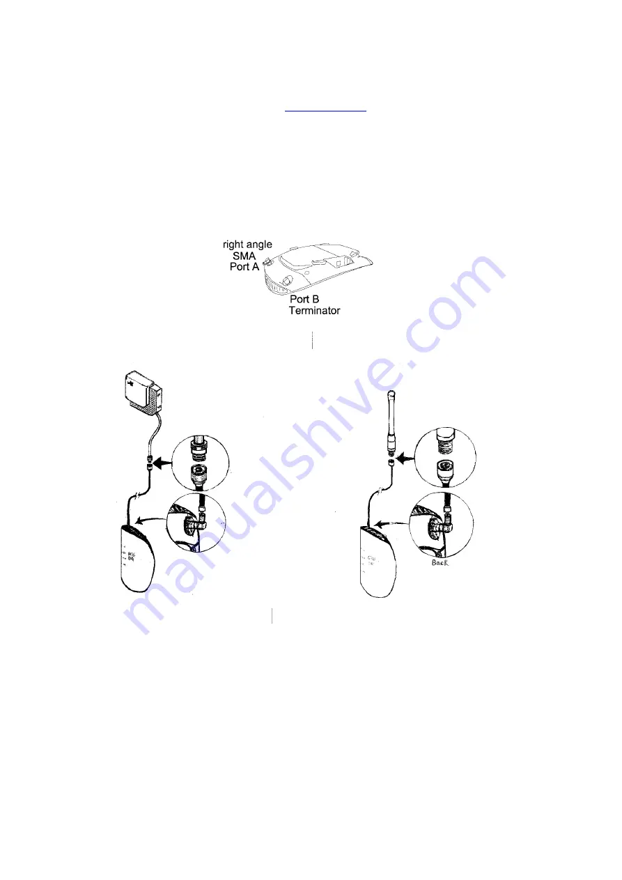
access point, remember to use only the A-side connector on the access point, on the right when properly
installed. B-side install a terminator at the same time.
1
Position the antenna so that there are minimal obstacles between it and any client with which it will
communicate. While maintaining a direct line of sight between the antenna and a client is not strictly
necessary, such an arrangement helps to ensure a strong signal. Ensure that access is available for
routing the antenna cable from the antenna to the access point.
2
If they are installed, remove both arms of standard detachable antenna, making sure not to handle the
tips of antenna.
3
Connect one end of the optional antenna cable to the antenna and secure the antenna in place.
4
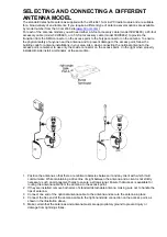
Connect the free end of the antenna cable to the right-hand side connection on the access point, as
shown in the illustration above.
5
Make certain that the antennas and antenna masts are appropriately ground to prevent injury or
damage from lightning strikes.
Summary of Contents for WL-464
Page 8: ......


