background image

 
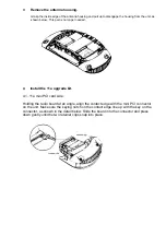
4.2. Antenna module side:


1  Align the antenna module with the snaps and posts on the unit and press until the 

module snaps firmly into place. 

2  Align the cables to be routed through the slots in the unit. 
3  After the cables are aligned, press them down out of the way inside the housing.    


Replace the back cover. 


Make sure that the cables are tucked away inside the housing so that they do not obstruct 
the cover. Align the back cover with the unit and settle the cover into place. Tighten the 
four screw.


Attach the antennas. 


Being careful not to touch the antenna tips, screw the antennas onto the SMA connectors 
and hand tighten them. After network startup , you may need to adjust the antennas to 
fine tune radio coverage.


Reinstall the access point. 


Reconnect the Ethernet cable and reattach the access point to the wall mounting plate. 
Adjust the antennas to improve the radio signal, if necessary.


Summary of Contents for WL-464

Page 1: ...upgrade kit contains these items One antenna module One 802 11a mini PCI Radio Module Two cables connect the antenna module and mini PCI card by direct soldering 1 Detach and disconnect the access point If the access point is mounted on the wall turn the unit counterclockwise to disengage it from the mounting plate Disconnect the Ethernet cable Place the access point face down on a static free sur...

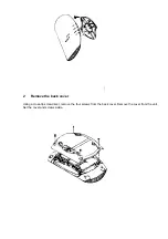
Page 2: ...2 Remove the back cover Using a cross tip screwdriver remove the four screws from the back cover Remove the cover from the unit Set the cover and screws aside ...

Page 3: ...4 Install the 11a upgrade kit 4 1 11a mini PCI card side Holding the radio board at an angle align the contact edge with the mini PCI connector on the unit Make sure the keying notch on the contact edge line up with the key on the connector as shown in the detail below Slide the board into the connector and press down gently until the two retainer clips snap into place ...

Page 4: ...away inside the housing so that they do not obstruct the cover Align the back cover with the unit and settle the cover into place Tighten the four screw 6 Attach the antennas Being careful not to touch the antenna tips screw the antennas onto the SMA connectors and hand tighten them After network startup you may need to adjust the antennas to fine tune radio coverage 7 Reinstall the access point R...

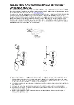
Page 5: ...to the access point remember to use only the A side connector on the access point on the right when properly installed B side install a terminator at the same time 1 Position the antenna so that there are minimal obstacles between it and any client with which it will communicate While maintaining a direct line of sight between the antenna and a client is not strictly necessary such an arrangement ...

Page 6: ... the following measures Reorient or relocate the receiving antenna Increase the separation between the equipment and receiver Connect the equipment into an outlet on a circuit different from that to which the receiver is connected Consult the dealer or an experienced radio TV technician for help This device complies with Part 15 of the FCC Rules Operation is subject to the following two conditions...

Page 7: ...ware not to provide information to the end user regarding how to install or remove this RF module in the users manual of the end product which integrate this module The users manual for end users must include the following information in a prominent location IMPORTANT NOTE To comply with FCC RF exposure compliance requirements the antenna used for this transmitter must be installed to provide a se...

Page 8: ......

Reviews: