


Network diagram
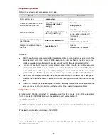
Figure 44-6
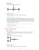
Network diagram for user-defined ACL
C
ctive from 8:00 to 18:00 everyday.
acket whose source IP address is 192.168.0.1 from 8:00 to 18:00
everyday (provided that VLAN-VPN is not enabled on any port). In the ACL rule, 0806 is the ARP
mask of the rule, 16 is the protocol type field offset of the internally processed
r-5000] rule 1 deny 0806 ffff 16 c0a80001 ffffffff 32 time-range test
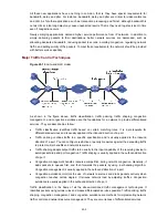
net 1/0/1. The IP address of PC 1 is 3001::1/64.
onfigure an ACL to filter packets that PC 1 sends to 3002::1/64 from 8:00 to 18:00 everyday.
onfiguration procedure
# Define a periodic time range that is a
<Sysname> system-view
[Sysname] time-range test 8:00 to 18:00 daily
# Define ACL 5000 to deny any ARP p
protocol number, ffff is the
Ethernet frame, c0a80001 is the hexadecimal form of 192.168.0.1, and 32 is the source IP address field
offset of the internally processed ARP packet.
[Sysname] acl number 5000
[Sysname-acl-use
# Apply ACL 5000 on Ethernet 1/0/1.
[Sysname] interface Ethernet1/0/1
[Sysname-Ethernet1/0/1] packet-filter inbound user-group 5000
IPv6 ACL Configuration Example
Network requirements
PC 1 and PC 2 connect to the switch through Ether
C
Network diagram
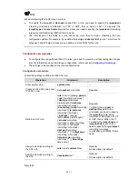
Figure 44-7
Network diagram for IPv6 ACL configuration
C
# Define a periodic time range that is active from 8:00 to 18:00 everyday.
onfiguration procedure
44-18