Setting Up the Switch Ports
4-11
Setting Up the Switch Ports
With the Switch Management screen displayed,
choose the management level
Port
. Choose the
appropriate port, then select the SETUP button.
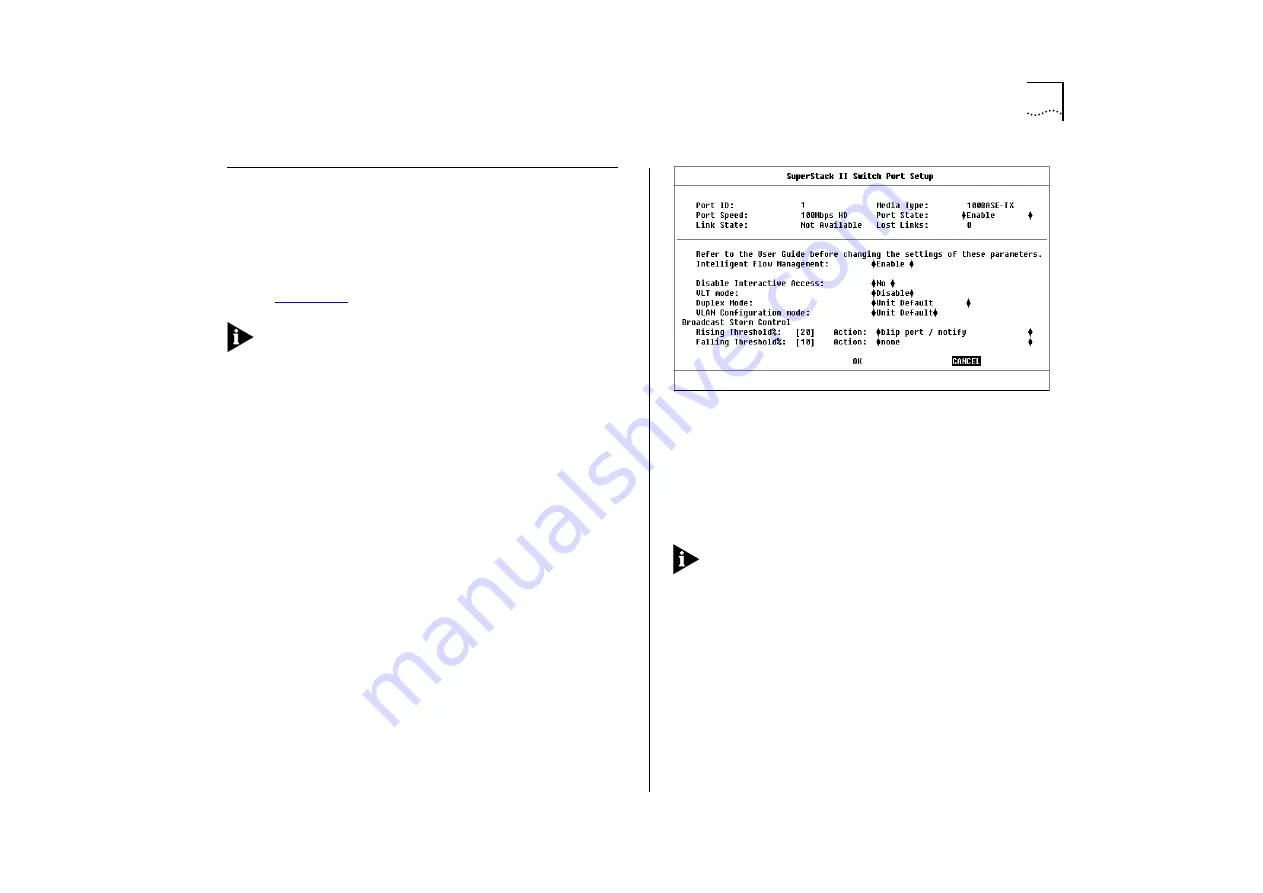
The Port Setup screen is displayed, as shown in
.
If the port is an ATM OC-3c Module port, the ATM
Port Setup screen is displayed. For more informa-
tion, refer to the “SuperStack II Switch ATM OC-3c
Module User Guide”.
The Port Setup screen shows the following fields:
Port ID
This read-only field shows the ID of the port
you have chosen to set up.
Media Type
This read-only field shows the media
type of the link connected to this port.
Port Speed
This read-only field shows the speed
and duplex mode of the link; HD indicates Half
Duplex, FD indicates Full Duplex.
Port State
Enable / Disable
This field allows you to
enable or disable the port. To prevent unauthorized
access, we recommend that you disable any unused
ports.
Link State
Present / Not Available
This read-only
field shows the state of the link:
■
Present
— The port is operating normally
■
Not Available
— The link has been lost
Figure 4-11
Port Setup screen
Lost Links
This read-only field displays the number
of times the link has been lost since the Switch was
last reset. If the number in this field is not zero, you
should check your cables and replace any that may
be damaged.
If the port is directly connected to an endstation,
the Lost Links counter increments each time the
endstation goes through a power-off/on cycle.
Intelligent Flow Management
Enable / Disable
This field allows you to enable or disable Intelligent
Flow Management (IFM). IFM minimizes packet loss
which can occur with conventional switches.
Intelligent Flow Management should be disabled if
the port is connected to a repeated segment where
the traffic is mainly local to that segment.
Summary of Contents for SuperStack II 3000 TX
Page 13: ...Network Configuration Examples 1 5 Figure 1 2 Increasing port density with the Switch 3000 TX ...
Page 14: ...1 6 CHAPTER 1 GETTING STARTED Unit Overview Front Figure 1 3 Switch 3000 TX front view ...
Page 16: ...1 8 CHAPTER 1 GETTING STARTED Unit Overview Rear Figure 1 4 Switch 3000 TX rear view ...
Page 20: ...1 12 CHAPTER 1 GETTING STARTED ...
Page 23: ...Configuration Rules with Full Duplex 2 3 Figure 2 1 Fast Ethernet configuration rules ...
Page 96: ...5 28 CHAPTER 5 ADVANCED MANAGEMENT ...
Page 122: ...C 6 APPENDIX C TROUBLE SHOOTING ...
Page 123: ...D PIN OUTS Null Modem Cable 9 pin to RS 232 25 pin PC AT Serial Cable 9 pin to 9 pin ...
Page 124: ...D 2 APPENDIX D PIN OUTS Modem Cable 9 pin to RS 232 25 pin RJ45 Pin Assignments ...
Page 136: ...6 GLOSSARY ...


