


90
C
HAPTER
7: R
EDUNDANCY
IN
THE
C
ORE
B
UILDER
7000 F
AMILY
ATM S
WITCH
Providing
Redundancy for
Various Power Loads
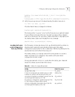
This section describes when redundant switch cards and redundant
power supplies can be used in a CoreBuilder switch.
In order to determine whether a redundant switch card and/or an
redundant power supply can be used in a CoreBuilder switch, the total
power consumption of all installed cards must be examined. According to
the total power consumption, there are three possibilities, as the
following examples illustrate:
Installation I:
The total power consumption of a single switching card
(that is, no redundant card installed) and all interface cards exceeds 90A.
In this case, a Dual 90A supply is required so that the second power
supply cannot be redundant. A redundant switch card can be installed.
This “heavy load” installation is illustrated by the first example installation
in Table 21.
Installation II:
The total power consumption of two switching cards
(i.e., redundant card installed) and all interface cards exceeds 90A but
without the second switching card the consumption is less than 90A. In
this case, either a redundant switch card or a redundant power supply
can be installed, but not both. This “medium load” installation is
illustrated by the second example installation in Table 21.
Installation III:
The total power consumption of two switching cards
and all interface cards does not exceed 90A. In this case, both a
redundant switch card and a redundant power supply can be installed.
The light load installation is illustrated by the fourth example installation
in Table 21.
In all installations that do not include multiple CB7600 cards both
redundant switch cards and redundant power supplies can be installed.
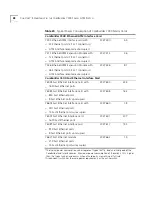
Other applications
■
CB7000 Switch Card
■
4 X 7262 Ethernet/ATM Interface Card
Single 90A
Single 90A
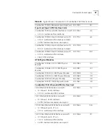
Table 21
Required Power Supply for Various Installations (continued)
Summary of Contents for CoreBuilder 7000
Page 8: ......
Page 20: ...20 CHAPTER 1 OVERVIEW...
Page 54: ...54 CHAPTER 5 POWER ON...
Page 96: ...96 CHAPTER 8 TROUBLESHOOTING...
Page 100: ...100 APPENDIX A ATM SWITCH FA 24 CELL SWITCHING MODULE SPECIFICATIONS...
Page 104: ...104 APPENDIX B SAFETY INFORMATION...
Page 122: ...122 APPENDIX D CABLING REQUIREMENTS...
Page 128: ...128 APPENDIX E TECHNICAL SUPPORT...
Page 148: ...148 INDEX...