68
C
HAPTER
7: M
AINTENANCE
FOR
THE
7-S
LOT
C
HASSIS
Removing a –48-volt DC Power Supply
The CoreBuilder 9000 Enterprise Switch 7-slot chassis
can accommodate up to two –48-volt DC power
supplies.
To remove a –48-volt DC power supply from a 7-slot
chassis:
1
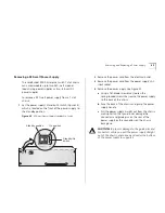
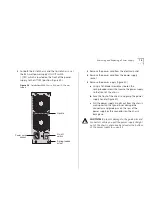
Set the power supply’s Standby/On switch (Figure 28),
which is located on the side of the power supply, to
the Standby position.
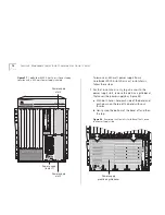
Figure 28
–48-volt
DC Power Supply Standby/On Switch
2
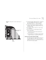
To protect the power supply that you want to remove,
turn off the building’s power source circuit breaker.
3
Remove each wire from the DC power source
electrical outlet.
4
Remove the 8 AWG wires from DC input connector
on the –48-volt DC power supply.
a
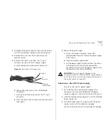
Label the polarity of both ends of each wire
(Figure 29).
Figure 29
Label Each 8 AWG Gauge Wire
b
Loosen the three wires with a slotted-blade
screwdriver.
c
Gently pull the three wires out of the DC input
connector.
d
Place the wires aside until you are ready to connect
them again.
INPUT RA
TING
-48
V /27A
ST
ANDBY
ON
-48V
0V
ST
ANDBY
ON
Standby/On
switch
On position
Standby position
-48-volt DC
Protective
earth ground
0V
(zero volt)
Summary of Contents for 3CB9E7 - CoreBuilder 9000 Chassis Switch
Page 54: ...54 CHAPTER 4 COREBUILDER 9000 ENTERPRISE SWITCH MODULES...
Page 60: ...60 CHAPTER 5 START THE SWITCH...
Page 74: ...74 CHAPTER 7 MAINTENANCE FOR THE 7 SLOT CHASSIS...
Page 88: ...88 CHAPTER 8 MAINTENANCE FOR THE 8 SLOT CHASSIS AND THE 16 SLOT CHASSIS...
Page 96: ...96 APPENDIX A SPECIFICATIONS...
Page 112: ...112 APPENDIX C INTELLIGENT POWER SUBSYSTEM...
Page 118: ...118 APPENDIX D TECHNICAL SUPPORT...


