


Installing the Switch 1000
2-5
Wall Mounting
A single Switch can be wall-mounted.
CAUTION:
Disconnect any cables from the unit
before continuing. Remove self-adhesive pads from
the underside of the unit if they have been previ-
ously fitted.
1
Place the Switch the right way up on a hard flat sur-
face, with the front facing towards you.
2
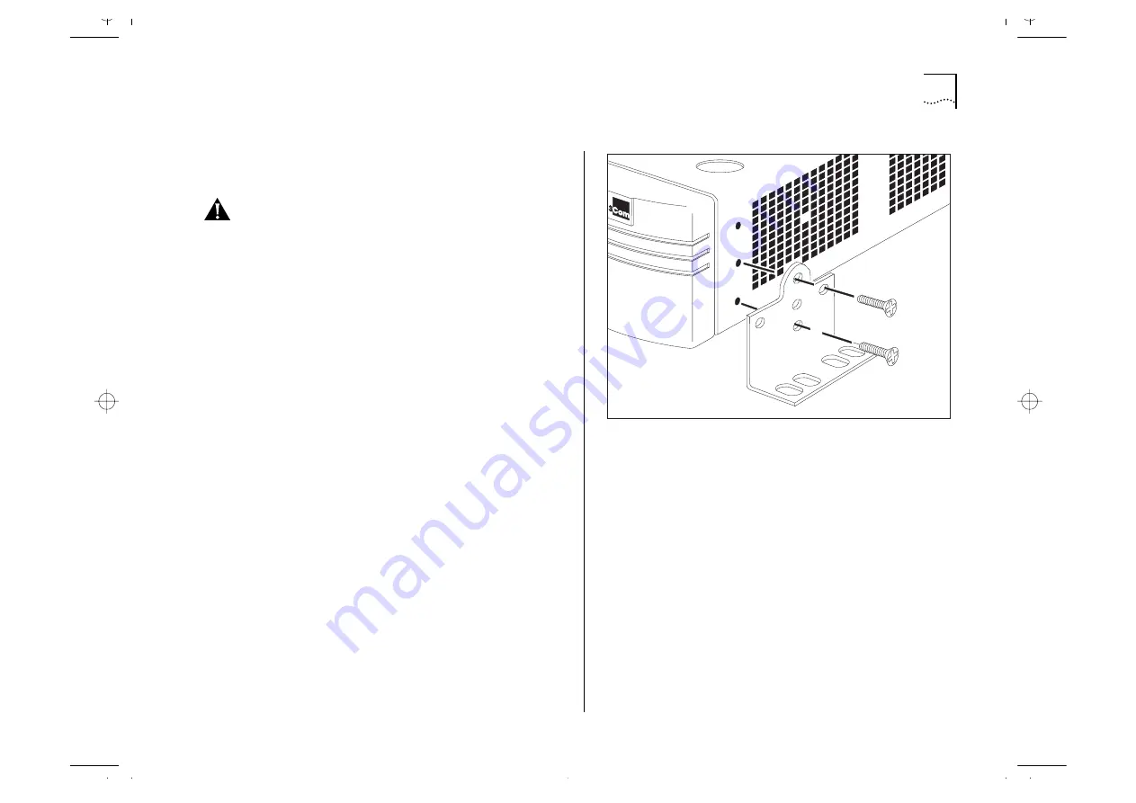
Locate a mounting bracket over the mounting
holes on one side of the unit, as shown in
Figure 2-3.
3
Insert the two screws and tighten with a suitable
screwdriver.
4
Repeat for the other side of the unit.
5
Ensure that the wall you are going to use is smooth,
flat, dry and sturdy. Attach a piece of plywood,
approximately 305mm x 510mm x 12mm (12in. x
20in. x 0.5in.) securely to the wall if necessary, and
mount the Switch as follows:
a
Position the base of the unit against the wall (or
plywood) ensuring that the ventilation holes face
sidewards. Mark on the wall the position of the
screw holes in both wall brackets. Drill the four
holes.
b
Using suitable fixings and screws (not provided),
attach the Switch unit securely to the wall or ply-
wood.
c
Connect network cabling.
Figure 2-3
Fitting a bracket for wall mounting
Summary of Contents for 1000
Page 20: ...1 12 CHAPTER 1 GETTING STARTED Unit Overview Rear Figure 1 5 Switch 1000 rear view...
Page 24: ...1 16 CHAPTER 1 GETTING STARTED...
Page 27: ...Configuration Rules with Full Duplex 2 3 Figure 2 1 Fast Ethernet configuration rules...
Page 104: ...5 30 CHAPTER 5 ADVANCED MANAGEMENT...
Page 130: ...C 6 APPENDIX C TROUBLE SHOOTING...
Page 131: ...D PIN OUTS Null Modem Cable 9 pin to RS 232 25 pin PC AT Serial Cable 9 pin to 9 pin...
Page 144: ...6 GLOSSARY...


