background image

8

9

2VV.

 Creating innovative solutions for you and your business since 1995.

ver.1 31-05-21

6. INSTALLATION

6.1 CHOOSING THE PLACE

It is recommended that installation of a ventilation 

system be pepared by an HVAC designer


             TECHNICAL INFORMATION

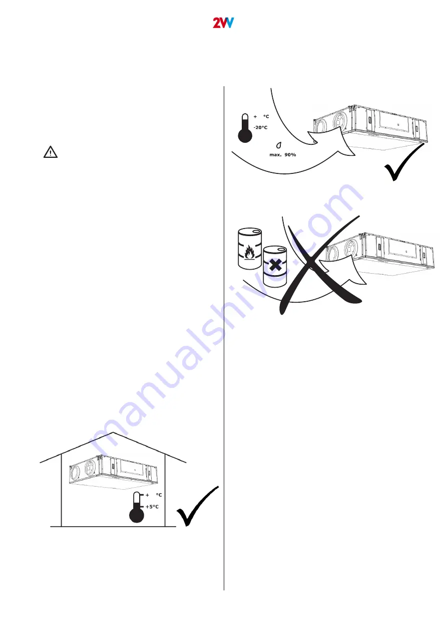
The unit is designed to be operated in a dry indoor 

environment (relative humidity not exceeding 80%) 

and at an ambient temperature in the range from 

+5°C up to +40°C.

The unit is designed for transporting standard at

-

mospheric air that is free of dust, grease, chemical 

emissions and other impurities. 

Condensation within the unit:

If the unit is placed in an attic space (temperatures may 

approximate  outdoor  temperatures),  it  is  necessary  for 

the unit to run continuously. If the unit can be turned off 

manually by the user or an automatic timer, it is necessa

-

ry to install airtight dampers with emergency functioning 

on the intake and exhaust ducts. The dampers will ensure 

that no air from the warm parts of the building will flow 

through the unit (stack effect). If no dampers have been 

installed, there will be a risk of condensation within the 

unit and exterior ducts at the time the unit is deactivated. 

This may also result in cold exterior air flowing into the 

building. In that case condensation can also occur within 

the intake and exhaust ducts or even in valves placed in 

rooms. If the unit is not running for a long period of time 

during  winter,  the  intake  and  exhaust  ducts  should  be 

closed so that the above effect does not occur after this 

period. If the unit is placed in a moist area (e.g. a laundry 

room), condensation On the external parts of the unit may 

occur when combined with low exterior temperatures. If 

condensation occurs outside the unit, increase the venti

-

lation in the surroundings of the unit.

40

40

The unit is not designed to filter air containing combus

-

tible or flammable particles, chemical fumes, coarse dust, 

carbon, grease, poisons, bacteria, etc.

The IP protection level of the unit in the ducts is IP 20

Summary of Contents for DAPHNE

Page 1: ...ver 1 31 05 21 EN DAPHNE FLAT INSTALLATION ...

Page 2: ...r business since 1995 ver 1 31 05 21 1 BEFORE STARTING 3 2 UNPACKING 4 3 MAIN COMPONENTS 5 4 DIMENSIONS 6 5 TECHNICAL PARAMETERS 7 6 INSTALLATION 8 7 COMMISSIONING 19 8 MAINTENANCE 20 9 TROUBLESHOOTING 21 10 LIQUIDATION PROCEEDINGS 24 11 CONCLUSIONS 25 ...

Page 3: ... Keep the manual in a safe place for future reference The manual is an integral part of the product Declaration of conformity The product has been designed produced an marketed in compliance with all the applicable provisions and abides to the provisiones of the European Parliament and Council including the amendments under which it has been classified It is safe under normal conditions and under ...

Page 4: ...ing the product check that the units and accessories are in order If you have any doubts contact the supp lier Never try to operate a damaged ventilation unit In the event that you decide not to unpack the ventilation unit immediately after delivery the product must be stored in a dry interior with a temperature ranging from 5 C up to 40 C maximum This product is not intended for use by persons in...

Page 5: ...scher Filter Filter Regulation die Regulation Condesate exhaust Kondensatausscheidung Afterheater Nachheizeinrichtung DX CO By pass flap By pass Klappe Preheater Vorwärmer Operational diagram Funktionsschema Fan Ventilator Heat exchanger Wärmetauscher Filter Filter Regulation die Regulation Condesate exhaust Kondensatausscheidung Afterheater Nachheizeinrichtung DX CO By pass flap By pass Klappe Pr...

Page 6: ...IONS A mm O mm B mm C mm D mm E mm F mm G mm H mm I mm J mm K mm L mm M mm N mm HRDF1 030 1188 1135 5 797 281 5 30 5 10 1160 652 Ø8 Ø160 355 5 171 139 403 242 HRDF1 050 1432 1347 5 885 322 5 30 5 10 1380 702 Ø8 Ø200 400 5 195 157 517 285 HRDF1 070 1646 1547 5 1065 364 5 30 5 10 1580 902 Ø8 Ø250 508 228 180 619 326 ...

Page 7: ...30 50 60 0 35 2 6 Type Voltage V Frequency Hz Power kW Total current A HRDF 030 230 50 60 1 4 7 3 HRDF 050 230 50 60 2 2 10 7 HRDF 070 230 50 60 2 7 13 Type Voltage V Frequency Hz Power kW Total current A HRDF 030 230 50 60 2 6 12 6 HRDF 050 230 50 60 3 14 2 HRDF 070 400 50 60 4 10 4 Type Voltage V Frequency Hz Power kW Total current A Speed r min IP Insulation class HRDF 030 230 50 60 120 0 87 32...

Page 8: ...cts The dampers will ensure that no air from the warm parts of the building will flow through the unit stack effect If no dampers have been installed there will be a risk of condensation within the unit and exterior ducts at the time the unit is deactivated This may also result in cold exterior air flowing into the building In that case condensation can also occur within the intake and exhaust duc...

Page 9: ...A B C HRDF1 030 min 450 mm min 850 mm min 850 mm HRDF1 050 no possible no possible no possible HRDF1 007 no possible no possible no possible 0 mm A A B B C C 6 1 1 Installation distance These dimensions are recommended for servicing access Installation on the wall possible only for HRDF1 030 The unit can only be installed in a position where the condensate drain is pointing downwards These dimensi...

Page 10: ...sponds to that of the distribution system The unit should be installed so as to provide access for maintenance service or disassembly This includes in particular access to inspecting the dampers flaps and their opening access to the cover of the control unit s cabinet to the cover of the of the air filter 6 1 2 Safe installation distance ATTENTION 6 INSTALLATION Any other position is forbidden 6 1...

Page 11: ... two more people to hold it Place the unit horizontally and then tilt it 3 to drain the condensate When installing on the wall place the unit horizontally The unit can only be installed in a position where the con densate drain is pointing downwards 6 INSTALLATION Drill the holes in the ceiling on the wall check the strength of the material and fasten the unit to the side brackets with the ZTZ M8 ...

Page 12: ...mm READ CAREFULLY 6 2 1 Flexible connection Connect the ducts to the exhaust and the suppl collars using flexible connections to stop the transfer of vibrati ons it will allow easier removal of the unit from the installa tion place when servicing Typ DN HRDF1 030 Ø160 HRDF1 050 Ø200 HRDF1 070 Ø250 6 2 3 INSTALLATION OF A FILTER BOX IN THE DUCT If unit is equiped with preheating then it is necessar...

Page 13: ...ry core e g 25 c and 35 c between the inside air and the outside air with a relative humidity above 60 Therefore we recommend that you install a second during summer condensate drain especially for chilled air conditioning buildings located in tropical climates The second condensate drain properly connect to the drain pipe Improper connection of the siphon may cause flooding and damage to the heat...

Page 14: ... the mains with a tem perature resistant rigid insulated cable that com plies with the local regulations Any intervention or modifications to the internal elect rical connection are forbidden and shall result on loss of warranty The correct operation of the unit can be guaranteed only with the use of original accessories Should it be necessary to install a sensor or control device in the unit or i...

Page 15: ... diagram for connection and according to the markings of the termi nals DO NOT MISS The connection diagram is glued to the internal side of the removable lid of the regulator box Each element must be connected using an original ca ble or cable as per the specification for each element To open the lid of the regulator box you will need TORX22 key See picture 6 INSTALLATION L sup N PE L1 L2 L3 N PE ...

Page 16: ...postabile SMU heater cooler Řídící signál nastavitelné SMU heater cooler Spatial sensor Внутренний датчик Czujnik przestrzenny Sensore ambientale Prostorové čidlo teploty Flap inlet fresh air Клапан свежего воздуха Klapa świeżego powietrza Aletta Aria fresca Klapka pro čerstvý vzduch Flap outlet Клапан отработанного воздуха Klapa wydechu Aletta Scarico Klapka pro odvodní vzduch N Neutral Entrée 24...

Page 17: ...he unit according to the level of relative humidity in the air Limit values must be set for the sensor PLEASE NOTE The accessories must be powered with their with their own external supply For details on the power supply refer to the docu mentation of the given accessory PREHEAT W PUMP BOOST IT CS silanie Punto di miscelazione alimentazione SMU napájení nia SMU heater Segnale di controllo impostab...

Page 18: ...to a wall or other surface If the connectors and cables aren t connected immedi ately after installing the unit protect them with insulat ing tape against mechanical damage or short circuit The cable connectors must not come into contact with water or any other liquid 6 INSTALLATION MODBUS RTU A 25 B 26 28 or 66 GND 6 5 2 5 Movement sensor 6 5 3 Control unit To start the unit connect the remote co...

Page 19: ...the condensate drain is well connected to the drainage piping units with cooling that the connection complies with the instructions herein that no tools or other objects have been left inside the unit it could result damage CAUTION Any intervention or modifications to the internal connection are forbidden and shall result on loss of warranty We recommend using the accessories we supply In case of ...

Page 20: ...ilters After the set filter clogging check period has expired the controller displays a warning about the need to check or replace the air filter ATTENTION If the filters are not changed properly the heat recovery unit may be damaged 8 MAINTENANCE b replacing the filter from the bottom cover open the designer cover replace filters unscrew the screws The cover is not secured by a fall protection sy...

Page 21: ...ot clean the unit with following Sharp objects aggressive chemicals solvents abrasive cleaning products pressured water pressured air or steam 9 TROUBLESHOOTING Description Unit s behav iour Likely problem Solution 4 Supply fan error Unit is not working Overheated fan or defect on thermal contact of inlet fan Determine the cause of the overheating defective bear ing short circuit or replace the en...

Page 22: ...C is around 10kΩ 25 Room temperature sensor failure T_Room Unit is venti lating Room temperature sen sor failure Check that the sensor is correctly connected to the electronics or test it measuring its resistance the resistance value at 20 C is around 10kΩ 32 Air quality sensor failure Unit is venti lating Defective air quality sensor Check that the quality sensor is connected correctly or check t...

Page 23: ...tly on the fuse ATTENTION When the power supply is resumed after an outage the unit returns to the status it was before the outage The unit always remembers its operational status and settings If you aren t able to find or remove the cause of the malfunction or if the repairs require an intervention on the device contact an authorised service The service of internal components must be done only by...

Page 24: ...the actions taken to fix it IF YOU CAN T FIX A MALFUNCTION 10 DECOMMISSIONING THE PRODUCT LIQUIDATION Contact the supplier If you can t fix a malfunction Render the unit useless before its disposal Older units also have materials that can be reused Take them to a collection yard It is recommended to have the unit disassembled in a specialised facility so that the recyclable materials may be reused...

Page 25: ...r installation and operation contra ry to the manual and the common practice of installation and operation of ventilation devices and regulations systems 11 CONCLUSIONS Read and observe the instructions herein for a safe and proper use of the unit Do not hesitate to contact our sales or technical support department in case of any query or request for explanation ...

Page 26: ...CONTACT Address 2VV s r o Fáblovka 568 533 52 Pardubice Czech Republic Internet http www 2vv cz ...

Reviews: