


Assembly Instructions Beta Prusa Minimal
30/05/13
First you should file a flat onto the motor shaft so that the gear will have a good grip on it.
Then secure the motor with three M3 x 12 mm screws and fitting washers onto the Wades
body, but don't completely fasten the screws yet.
Bolt the prepared Idler with a M3 x 30 mm screw and fitting washers and a nut onto the
Wades Idler. Then fold the M4 screws with the springs over the Idler as shown in the picture
above.
Put a bearing into the depression on both sides of the Wades body.
Assembly step 3.4
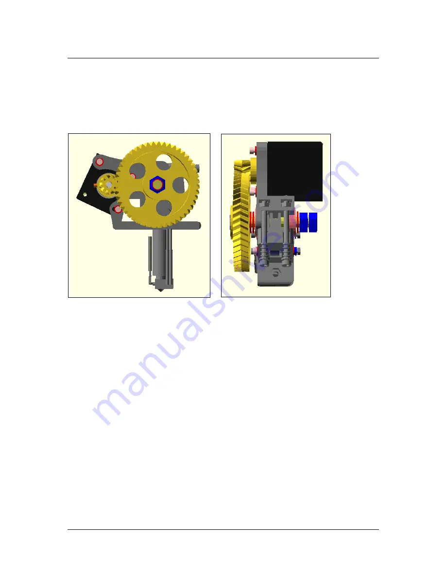
Put the M8 Nyloc nut into the big gear and screw it onto the longer part of the Hyena drive
screw. Also put two M8 washers onto the drive screw.
Then put the small gear onto the motor shaft and secure it with a M3 x 8 mm grub screw and
simultaneous put the drive screw with the big gear through the bearings on the wades body.
Check that both gears can turn without problems and adjust the motor so that both gears
mesh together and can turn without much play. Now secure the motor completely.
As the last step secure the drive screw with a washer and two M8 nuts on the other side.
Page 41 / 57


