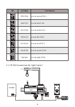
-5-
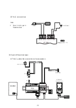
Note:
1. When DT-RLC connect Electronic
lock, the jumper position in 1-2.
2. When DT-RLC connect E-magnetic
lock, the jumper position in 2-3.
Jumper position in 1-2
1 2 3
GND
S1
S2
12V
NC
COM
NO
GND
E-lock
Exit Button
*
DT-RLC
+
-
DT-RLC connect lock
5.4 External Power Supply powered lock connection
BUS(IM) BUS(DS)
PC6
Exit Button
GND
S1
S2
12V
NC
COM
NO
GND
AC~
monitor
-
+
L1 L2 PL S+ S-
adaptor for the lock
E-lock
1# Camera
(Device Address:0)
-
+
NO
POWER IN-USE
BUS
GND
COM NC
DT-RLC
2-WIRE SYSTEM
12V
S2
S1 GND
BUS
RISER
1
2
3
A. Power-on-to-unlock type:
1
2
3
ON
DIP
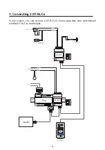
DT-RLC control the second lock of door station 1

