background image


51 


You can access the mDVR514M SYSTEM CONFIGURATION by clicking on the “SETUP” button from the 

DVRViewer application and login in using the default username and password of “admin” and “admin”. 

6.6.6.


DISCONNECT 


This button simply disconnects DVRViewer from the mDVR514M 


6.7.


PLAY ARCHIVE 


To playback recorded video, the media storage must be removed from the mDVR514M unit and plugged 

into your laptop / computer using the Mini USB Cable that was included with the purchase of your mDVR514M. 
 

Connect the Mini USB connector to the media storage device and the USB connector to your laptop / 

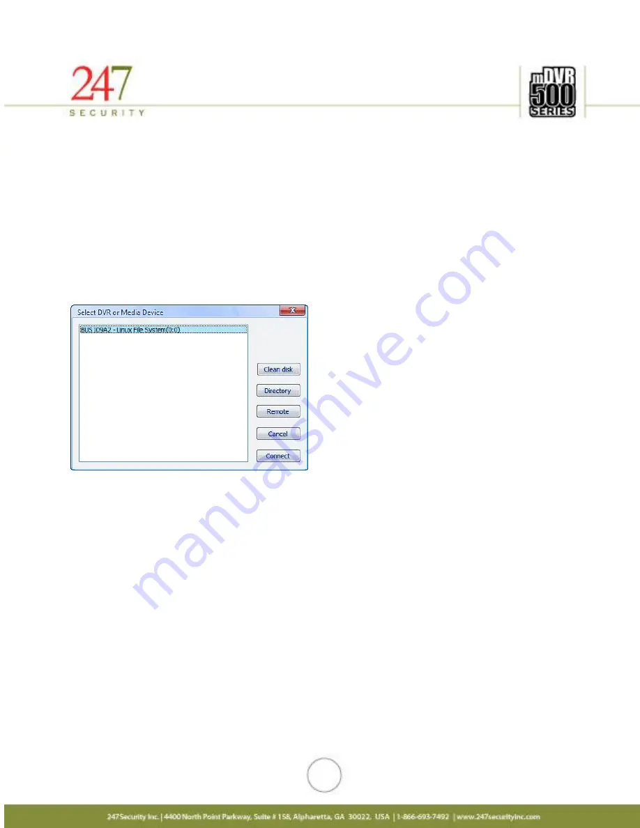
computer and start DVRViewer application. Once DVRViewer is running click on “Play” button and select “Play 
Archive” and you should se the following window. 


Select the media storage device from the list so that it’s highlighted and then click on “Connect” button. 
 

Summary of Contents for mDVR514M

Page 1: ...1 USER MANUAL mDVR514M Rugged Digital Video Recorder for In Vehicle Applications 4 Video Audio Channels 30 fps per Channel V11 0308 ...

Page 2: ...CTOR 2 2 5 GENERAL PURPOSE INPUT OUTPUT CONNECTOR 2 2 6 CAMERA 1 2 3 AND 4 CONNECTORS 2 2 7 WIFI CONNECTOR 2 2 8 RF MODEM CONNECTOR 2 2 9 GPS CONNECTOR 2 2 10 GENERAL PURPOSE INPUT OUTPUT CONNECTOR 2 2 11 G FORCE CONNECTOR 2 2 12 CELL MODEM CONNECTOR 2 2 13 10 100 BASE T W POE CONNECTOR 2 2 14 USB 2 0 CONNECTOR 2 3 CABLE REQUIREMENTS 2 3 1 POWER CABLE 2 3 2 EVENT MARKER CABLE 2 3 3 SENSOR ALARM CA...

Page 3: ...E 5 5 4 SHUTDOWN DELAY S 5 5 5 STANDBY TIME S 5 5 6 MAXIMUM FILE SIZE MB MAXIMUM FILE TIME S 5 5 7 MINIMUM AVAILABLE DISK SPACE MB 5 5 8 EVENT MARKER 5 5 9 PRE LOCK TIME S POST LOCK TIME S 5 5 10 STOP RECORDING WHEN PLAY BACK 5 5 11 STOP RECORDING WHEN LIVE VIEW 5 5 12 ENABLE FILE ENCRYPTION 5 5 13 FILE ENCRYPTION PASSWORD 5 5 14 ENABLE GPS 5 5 15 ENABLE TAB102 5 5 16 ENABLE SMART UPLOAD 5 5 17 EN...

Page 4: ... 5 10 1 DOWNLOAD CONFIGURATION 5 10 2 UPLOAD CONFIGURATION 5 10 3 UPDATE FIRMWARE MCU FIRMWARE 6 DVRVIEWER 6 1 INTRODUCTION 6 2 SOFTWARE CLIENT FEATURES 6 3 SYSTEM REQUIREMENTS 6 4 INSTALLATION 6 5 STARTING DVRVIEWER 6 6 LIVE VIEW 6 6 1 SELECTING SCREEN LAYOUT 6 6 2 CAMERA SELECTION 6 6 3 CAMERA MENU 6 6 4 SNAPSHOT 6 6 5 SETUP 6 6 6 DISCONNECT 6 7 PLAY ARCHIVE 6 7 1 SEARCH VIDEO BY CALENDAR AND TI...

Page 5: ...channel image quality control real time previewing on all channels alarm triggers sensor configuration easy retrieval and transfer of video files over WIFI LAN GPS tracking and much more In addition mDVR514M allows end users to independently manipulate these parameters for each camera if desired 1 2 SPECIFICATIONS ELECTRICAL Video Recording Resolution Each channel can be set independently using D1...

Page 6: ...be connected Indicators Ignition LED green Power LED green HDD activity LED green USB LED green Error LED red Video Lost LED red PHYSICAL POWER Housing Ionized Aluminum for rugged applications Form factor Depth 194 mm 7 625 inches Width 176 mm 6 875 inches Height 58 mm 2 313 inches Not including shock and vibration isolator Weight Typically approximately 1 3 kg 2 8 lb Not including shock and vibra...

Page 7: ...ction Ignition Signal Power Down Timer Software configurable delay power off signal from 1 120 minutes 50mA current draw in sleep mode after power down Power consumption Typical 12W 5 C 55 C DVR draws less than 24ma when off ENVIRONMENT Temperature range 30 C to 55 C 22 F to 131 F operating temperature Relative humidity 10 to 90 non condensing ...

Page 8: ...8 1 3 DIMENSIONS The dimensions used in the following 2 diagrams are in inches ...

Page 9: ...Removable Hot Swap Hard Drive USB Activity LED USB 2 0 Video Out Audio Out 10 100 Base T Power 8 24V DC IN Event Marker General Purpose I O Video Audio Input 12VDC Output USB 2 0 Wi Fi GPS C D C Communications Display Controller Record LED Error LED Video Lost LED HDD On Off Key lock G Force General Purpose I O ...

Page 10: ...tion Pin out 1 TX Transmit Data 2 TX Transmit Data 3 RX Receive Data 4 RX Receive Data 5 NC Not connected 6 COM Common 7 COM Common 8 COM Common 9 COM Common 2 1 2 USB 2 0 CONNECTOR Connector type 4 pin friction lock header 2 1 3 AUDIO OUT CONNECTOR Connector type RCA Jack Pin Number Signal Description Pin out Inside Audio Audio Signal Outside GND Ground Pin Number Signal Description Pin out 1 VCC...

Page 11: ... 2 GND RF Ground 2 2 2 GENERAL PURPOSE INPUT OUTPUT CONNECTOR 1 This connector provides 3 digital inputs The digital inputs are labeled as DI_6 DI_7 DI_8 End users can assign any sensors to one of these digital input signals up to 3 sensors can be wired to this connector This connector also provides 12VDC OUT on pin 4 with a built in 0 75A fuse Pin Number Signal Description Pin out 1 Input DI_6 2 ...

Page 12: ...ystem will then go through its normal shutdown procedures before completely powering down The GND Common DC ground signal should be connected to the vehicle common ground Pin Number Signal Description Pin out 1 ON OFF On Off Switch On when 6V VIN Off when 0V 0 5V 2 GND Ground 3 VIN Input voltage 8V 24VDC 4 GND Ground 2 2 5 CAMERA 1 2 3 AND 4 CONNECTORS The mDVR514M supports a maximum of 4 cameras ...

Page 13: ...L PURPOSE INPUT OUTPUT CONNECTOR 2 This connector provides 5 digital inputs and 1 digital output The digital inputs are labeled as DI_1 DI_2 DI_3 DI_4 DI_5 The digital output is labeled as DO_3 End users can assign any sensors to one of these digital input signals Up to 5 sensors can be wired to this connector Alternatively one alarm LED Siren etc is available on the digital output Pin Number Sign...

Page 14: ...cable Pin Number Signal Description Pin out 1 DI_0 2 GND 3 12V OUT 4 Output DO_0 5 Output DO_1 6 Output DO_2 2 2 10 G FORCE CONNECTOR This connector is used to plug in the included event marker cable Pin Number Signal Description Pin out 1 RS485 T 2 RS485 T 3 RS485 R 4 RS485 R 5 GND 6 5VDC OUT ...

Page 15: ...when ignition is in RUN ACC 2 3 2 EVENT MARKER CABLE A 15 ft cable is already connected to the Event Marker and pre wired to a 2X3 Molex connector the Molex connector will then connect to the event marker port on the back of the DVR The event marker uses 3 digital outputs for Video Lost Recording Power LED s and 1 digital input for the push button The push button is used for pre post trigger recor...

Page 16: ... 4 Orange Motion Sensor Connects to Motion Sensor of GP I O connector Pin 5 White Brown Output DO_3 Connects to Digital Output 3 of GP I O connector Pin 6 Blue GND Connects to GND of GP I O connector Pin 7 White Blue GND Connects to GND of GP I O connector Pin 8 2 3 4 CAMERA CABLE STP shielded twisted pair cable is the standard and will use 2X3 Molex plugs for connections making the installation s...

Page 17: ... audio from the video channels Connector Signal Description Picture RJ45 Connects to 10 100BASE T LAN connector 2 3 7 MINI USB CABLE This cable connects the mDVR removable storage media to your computer or laptop for video audio playback This is a standard USB 2 0 Type A to 5 Pin mini B Cable which should be no longer than 12 to 16 inches See section 6 for instructions on how to use the DVRViewer ...

Page 18: ...rdering and installing cameras in your vehicle Lens Angle of View Best focus distance Viewable distance 2 9mm 120 4 ft 10 ft 3 6mm 92 5 ft 12 ft 6 0mm 54 8 ft 20 ft 8 0mm 39 10 ft 28 ft 12mm 26 13 ft 35 ft 16mm 19 20 ft 56 ft Viewable distance means maximum range of the optimum standard ...

Page 19: ...19 ...

Page 20: ...or troubleshooting procedures 3 1 5 VIDEO LOST INDICATOR LED This LED is to notify operator when any of the enabled cameras loses video signal meaning the cable is cut or is not connected 3 1 6 USB ACTIVITY LED This LED is to notify the operator that there is USB activity which means that data files are being downloaded from the HDD to the USB thumb drive or that a firmware upgrade is in progress ...

Page 21: ...l video audio files and safely turn HDD power off 2 Wait until HDD Safe Removal LED stops flashing and stays off 3 Gently pull media storage out from the bay 4 Insert new media storage 5 Turn key to the Close position The mDVR514M will now turn the HDD power on detect the new media and start recording again 3 4 WIRELESS VIDEO RETRIEVAL Refer to SmartServer manual 3 5 REMOTE POWER CONTROL Future im...

Page 22: ...Y numbers on this screen for your record if needed 4 3 1 8 Left click on Use the following IP Address button 4 3 1 9 In the IP address window type 192 168 1 55 4 3 1 10 Left click mouse on Subnet mask and you should have 255 255 255 0 4 3 1 11 There should be no other numbers in the TCP IP properties 4 3 1 12 Left click on OK or Close 4 3 2 USING WINDOWS VISTA 4 3 2 1 Right click on the Network ic...

Page 23: ... 4 TCP IPv4 4 3 3 8 Left click on Properties 4 3 3 9 Record ANY numbers on this screen for your records if needed 4 3 3 10 Left click on Use the following IP Address button 4 3 3 11 In the IP address window type 192 168 1 55 4 3 3 12 Left click on Subnet mask and you should have 255 255 255 0 4 3 3 13 There should be no other numbers in the TCP IP properties 4 3 3 14 Left click on OK 4 3 3 15 Left...

Page 24: ...tion CD that is sent along with the unit 5 2 DVRVIEWER LOGIN The first screen that appears when you start the DVRViewer application will be the LOGIN screen If this is the first time logging in the default username and password will be admin and 247SECURITYINC Both the Username and password are case sensitive If you forget or lose your password please contact 247Security Inc Technical Support for ...

Page 25: ...figure the mDVR514M to meet your requirements The process is straightforward and easy to follow the DVR setup is divided into six major components SYSTEM CAMERA SENSOR NETWORK STATUS and TOOLS The system will already have been configured at the factory for your specific system requirements but of course can be updated as needed You can access the SYSTEM CONFIGURATION by clicking on the SETUP butto...

Page 26: ...N MENU The system configuration menu is where you configure general parameters such as the name of the DVR time zone shutdown delay etc Also the G Force set up parameters are here if the Drive Safe module is attached to the DVR ...

Page 27: ...trated by clicking on Play and selecting Live View you will see a list of all mDVR514M servers that you can select By Clicking on any selected DVR server name you gain access to that particular mDVR514M system The additional data to possibly input is the bus number as part of the text overlay Highlight the BUS001 in the server name box and change the bus name using letters numbers with a maximum o...

Page 28: ...en DVR enters standby mode many hardware components are shut down to conserve power recording of video is disabled and SmartServer upload occurs 5 5 6 MAXIMUM FILE SIZE MB MAXIMUM FILE TIME S The menu basically defines how video files are recorded on the removable hard drive s There are two modes that video files can be recorded 1 Video files can be recorded by file size Maximum File MB or 2 by fi...

Page 29: ...iles first The same process is on going until you have enough recording space 5 5 8 EVENT MARKER This drop down list will enable you to select which sensor to use for the event marker The Event Marker Sensor 1 is the default sensor to be used with the included event marker cable unless there is a required custom solution to use a different sensor 5 5 9 PRE LOCK TIME S POST LOCK TIME S Pre Lock Tim...

Page 30: ...e password will be requested This is an additional security feature to keep unauthorized users from viewing the video Note If the password is lost the video CAN NOT be retrieve 5 5 13 FILE ENCRYPTION PASSWORD If file encryption is enabled see above this is where the password is set Warning If you enable file encryption and forget your password you will NOT be able to play back your recorded video ...

Page 31: ...set at 1 it will display camera input 1 via the RCA video out port on the front of the DVR If 4 is selected it will display a QUAD view and include all 4 camera inputs via the RCA video out port 5 5 20 DRIVE SAFE G FORCE SET UP If the TAB102 option is checked as listed above the G Force parameters will then appear on the system set up page after a system re boot NOTE DO NOT CHANGE ANY OF THE BASE ...

Page 32: ...d 8 camera inputs configurations Each camera input can be configured individually to have different characteristics such as picture quality frame rate resolution recording mode etc You can select any camera by clicking on its tab where a sub menu is available for configuration ...

Page 33: ...can select from Each camera input can record in Continue Trigger by sensor Trigger by motion and Trigger by sensor motion modes 5 6 3 1 CONTINUE The DVR is continuously recording in the background no matter what It never stops unless the DVR is powered down or the storage media is removed from DVR Therefore video files are constantly generated in the background filling up the storage device It is ...

Page 34: ...were described above Therefore the DVR starts recording either by sensor or motion that have triggered programmable events 5 6 3 5 NO RECORDING This mode disables the camera input 5 6 4 RESOLUTION There are many modes available of video resolution and 704x480 being the highest Selecting the highest resolution will create larger files and shorten the storage recording time but provide a clearer ima...

Page 35: ...ximum compression but maintaining picture quality 5 6 7 BIT RATE The bit rate is also pre set from the manufacturer to the default setting of 1 Mbps Changing this setting will increase or decrease the picture quality the smaller the bit rate the smaller the file size but less picture quality the bigger the bit rate the bigger the file size and better picture quality 5 6 8 PICTURE QUALITY ...

Page 36: ...ation of the camera Values range from 1 to 10 1 being the lowest and 10 being highest 5 6 10 TRIGGERS The DVR has 6 digital inputs available to connect to sensors This triggers menu allows you to select which sensor s will trigger the recording process By placing a check in the Trigger box corresponding to the sensor number on its left will activate that sensor All sensors can be enabled simultane...

Page 37: ...eam Speed can be displayed in mph or km h If this option is not enabled GPS data is still recorded in a log file on the video storage media MiniTRACK is a software application combining recorded GPS data with GIS mapping to allow you to monitor vital vehicle information Track Stopping Idling and speeding occurrences Create custom reports Export data to other software for review and analysis MiniTR...

Page 38: ... to the event marker labeled Recording and Video Lost Digital Output 3 and 4 can be connected to external LEDs inside the vehicle using the mDVR514M sensor alarm cable harness You can also control the LED mode by clicking on the Mode drop menu and selecting either flashing by interval on or off when the event occurs 5 6 15 MOTION SENSITIVITY When using recording mode trigger by motion this option ...

Page 39: ... Screen Display is enabled Inverted defines how the sensor should work For instance if you check the box Inverted then the mDVR514M detects 0 as the active state of the sensor If the check box is un checked then the mDVR514M detects 1 as the active state of the sensor Please make sure you understand how your sensors work before connecting them to the digital inputs 5 7 1 SENSOR NUMBER Click on the...

Page 40: ... page Once setup is complete the DVR can be accessed via your wireless network If the SmartServer option is purchased the DVR can automatically upload video events upon wireless range of your access point For example if your vehicles are all equipped with the wireless option and you have purchased the SmartServer technology your vehicles upon returning from their route will automatically upload to...

Page 41: ...pports and the current DVR time as well as your local computer time The local computer time is extracted from your computer which is currently connected to the DVR The Synchronize DVR Time button will synchronize the DVR time with the local time on the connected laptop or computer The information below the Synchronize DVR Time button provides the user a general system health of the DVR as well as ...

Page 42: ...d will save you time when multiple mDVR514M systems need to be configured Once the DVR has been configured click the Download button to save your settings to a file on your desktop or a location of your choice Click the Download button and the following window will appear Select a folder location of your choice and click the Save button A file named mvdr cfg will be saved the chosen location You c...

Page 43: ...r name from the configuration file Note All previous video data on the DVR will be lost if you do an upload Note Download and Upload Configuration feature is not compatible between different versions of firmware this feature should only be used when deploying multiple DVRs with same hardware and software Installer would configure the first DVR and then download the configuration to his computer wh...

Page 44: ...gs there the previous settings will be lost It is recommended to click Continue so that you can verify all the new settings Click Close to close the DVR setup or Continue to make additional changes You may need to change the DVR Server Name at this point or adjust another specific setting relevant to the new vehicle or application 5 10 3 UPDATE FIRMWARE MCU FIRMWARE ...

Page 45: ...h is located in the middle of the power connector and the event marker connector c Browse for latest MCU file example v5 7 MDVR514MA57 hex d Update MCU e After about 30 seconds you should receive the following message MCU firmware update succeeds Please un plug FORCEON cable System reboot f Remove Force Power on plug and wait for about 50 seconds until DVR restarts g Click Close to close the Inter...

Page 46: ...y settings specially the DVR Server Name d Turn key lock to off position and wait until DVR powers off e Insert hard drive f Turn key lock to on position and wait until DVR boots up 7 Verify functionality a Launch Internet Explorer b Type http 192 168 1 100 to access DVR setup c Verify new settings d Go to Tools tab and click Download to save new working configuration of the bus and name the confi...

Page 47: ...se clicks A calendar is also available to allow users to search for video for the day and month required User can create custom video files by specifying Start and End Times using the Custom Clip feature and then save these files to their local hard drive User Management allows only the Admin user to gain complete access to the mDVR514M system such as configuration update maintenance copy delete v...

Page 48: ... a new password After logging in the following main screen will appear see below for description on the controls and buttons The controls and buttons in the main screen No Name Description 1 Play Brings up these options Live View Play Archive Play File 2 Disconnect Disconnects DVRViewer from a DVR or from a media storage 3 Setup Enters DVR setup 4 Users Enables user to create delete and modify use...

Page 49: ...ays video playback 20 Jump Forward 20 Seconds Jumps forward video playback 20 seconds 21 Fast Accelerates playback speed 22 One Frame Forward Advances one frame forward while in Pause mode during playback 23 Start Stop MiniTRACK Starts or stops the connection to the MiniTRACK server An Internet connection is needed for this connection To use this feature you must purchase the Video Track option 24...

Page 50: ... different screen layouts available 6 6 2 CAMERA SELECTION The function key F7 enables user to select camera by scrolling through the available cameras or you can simply use the mouse and click a specific camera to make it the active camera When audio is set to single channel mode the active camera is the only one playing audio 6 6 3 CAMERA MENU The camera menu can be opened by right clicking on a...

Page 51: ...ia storage must be removed from the mDVR514M unit and plugged into your laptop computer using the Mini USB Cable that was included with the purchase of your mDVR514M Connect the Mini USB connector to the media storage device and the USB connector to your laptop computer and start DVRViewer application Once DVRViewer is running click on Play button and select Play Archive and you should se the foll...

Page 52: ...CH VIDEO BY CALENDAR AND TIMELINE BAR Using the calendar you can select the date you wish to search for video files Bold Text Number indicates video is available on that date Allow a few seconds for the retrieval and listing of video that you can select on the timeline bar There are two modes that you can view the recorded video on the timeline bar 1 One Day Timeline bar can be set to One Day whic...

Page 53: ...red bars on the timeline bar 6 7 3 PLAY BACK CONTROL DVRViewer allows total control of the video being played back User can fast track or slow down video play back by using the Slow or Fast buttons User can also pause or resume video playback using the Pause Play button In addition to playback video frame by frame click on Pause Play button to pause the video playback first then click the One Fram...

Page 54: ...h custom start and end times User can move the pointer on the timeline bar to the desired time location and set this location as begin time by clicking on Start Time button Same procedure applies to setting the end time but clicking on End Time button Both Start Time and End Time boxes should now have the desired time stamps you selected to create your video file User can also manually input these...

Page 55: ...ing the video data so that it can be used in legal matters 6 8 PLAY FILE This button will prompt user to open a video clip previously saved on their hard disk CD DVD USB thumb drive etc using the Custom Clip feature All video and audio will start playing immediately and the standard playback controls as described in 6 4 3 are available for control of playback ...

Page 56: ...AGEMENT From the main screen click on Users to access the mDVR514M user management interface There are two types of users User with limited rights or Administrator with full access to the mDVR514M system A standard user with limited rights can preview and copy recorded video files from storage media A user setup with Administer rights can control configure copy and delete video update software and...

Page 57: ...ete users The default Administrator user called admin cannot be deleted 6 10 3 CHANGE USER PASSWORD Click on Change Password to change user s passwords You are required to enter the correct old password in order to assign a new password Note If you have forgotten the admin password than you will need to re install your DVRViewer application to reset the password back to the default setting ...

Page 58: ...ides several methods for contacting Technical Support listed below Visit our website at www 247securityinc com and click on Support Email us your questions directly to support 247securityinc com Calling our direct line Toll Free at 1 866 693 7492 ...

Page 59: ...s or damage with respect to the product it sells regardless or cause or origin its maximum liability shall not in any case exceed the purchase price of the product which shall be fixed as liquidated damages and not as a penalty and shall be the complete and exclusive remedy against the Seller By accepting the products to the fullest extent permitted by law Buyer assumes all liability for and agree...

Page 60: ...rns to the jurisdiction of the courts of the Province of Ontario and further agrees to commence any litigation which may arise hereunder in the courts in the Judicial District of York Province of Ontario 2009 247Security Inc All rights reserved The information in this publication is accurate in all respects at time of writing 247Security Inc cannot assume responsibility for any consequences result...

Reviews: