12
2.2.3.
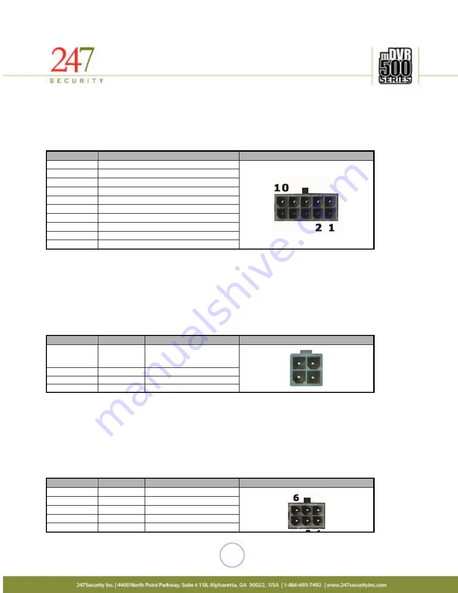
COMMUNICATIONS DISPLAY CONTROLLER (C.D.C.) CONNECTOR
This connector allows the user to connect a C.D.C. which is a LCD monitor with video out capabilities and
manual video controls including live view, playback, record start/stop, volume controls, and video status
indicators. (FOR FUTURE USE)
Pin Number
Signal Description
Pin out
1
Audio OUT GND
2
Audio OUT
3
Video OUT + / Video OUT RCA
4
Video OUT - / Video OUT GND
5
Turn Power ON
6
RS232 TXD
7
RS232 RXD
8
GND
9
+12VDC OUT
10
+3VDC Standby
2.2.4.
POWER INPUT CONNECTOR
The mDVR514M has a built-in Intelligent power switcher that can operate from +8V ~ +24V DC-IN. The
ON/OFF signal connects to the vehicle’s ignition signal. The mDVR514M uses this signal to trigger the power shut-
off delay and the timing circuitry. The mMVR514M will remain ON until the shut-off delay time has been reached.
The system will then go through its normal shutdown procedures before completely powering down. The GND
(Common DC ground) signal should be connected to the vehicle common ground.
Pin Number
Signal
Description
Pin out
1
ON/OFF
On/Off Switch
On when 6V ~ VIN
Off when 0V ~ 0.5V
2
GND
Ground
3
VIN
Input voltage (+8V~+24VDC)
4
GND
Ground
2.2.5.
CAMERA 1,2,3, AND 4 CONNECTORS
The mDVR514M supports a maximum of 4 cameras. These Micro-fit connectors are used to connect the
four camera inputs to the mDVR514M system (video and audio). Also included in each camera connection is
DV12V Out to power the camera. You can refer to the cover of the DVR for the PIN assignments of each connector.
If any of these cameras are not connected properly (for instance loose cables, unplugged etc…) than the
mDVR514M intelligently notifies the end-users with “NO VIDEO” on the preview screen. Camera inputs are labeled
CAMERA 1, CAMERA 2, CAMERA 3, and CAMERA 4.
Pin Number
Signal
Description
Pin out
1
MIC-IN
Microphone In
2
GND
Ground
3
Video+
Video In (+)
4
Video-
Video In (-)
5
+12VDC
+12VDC OUT


