background image

27

UHF Wireless Mic Installation

Automatic Transmitter Setup

Turn ON the transmitter.

Open the transmitter battery compartment to display the infrared (IR) 

port. (See page 28)

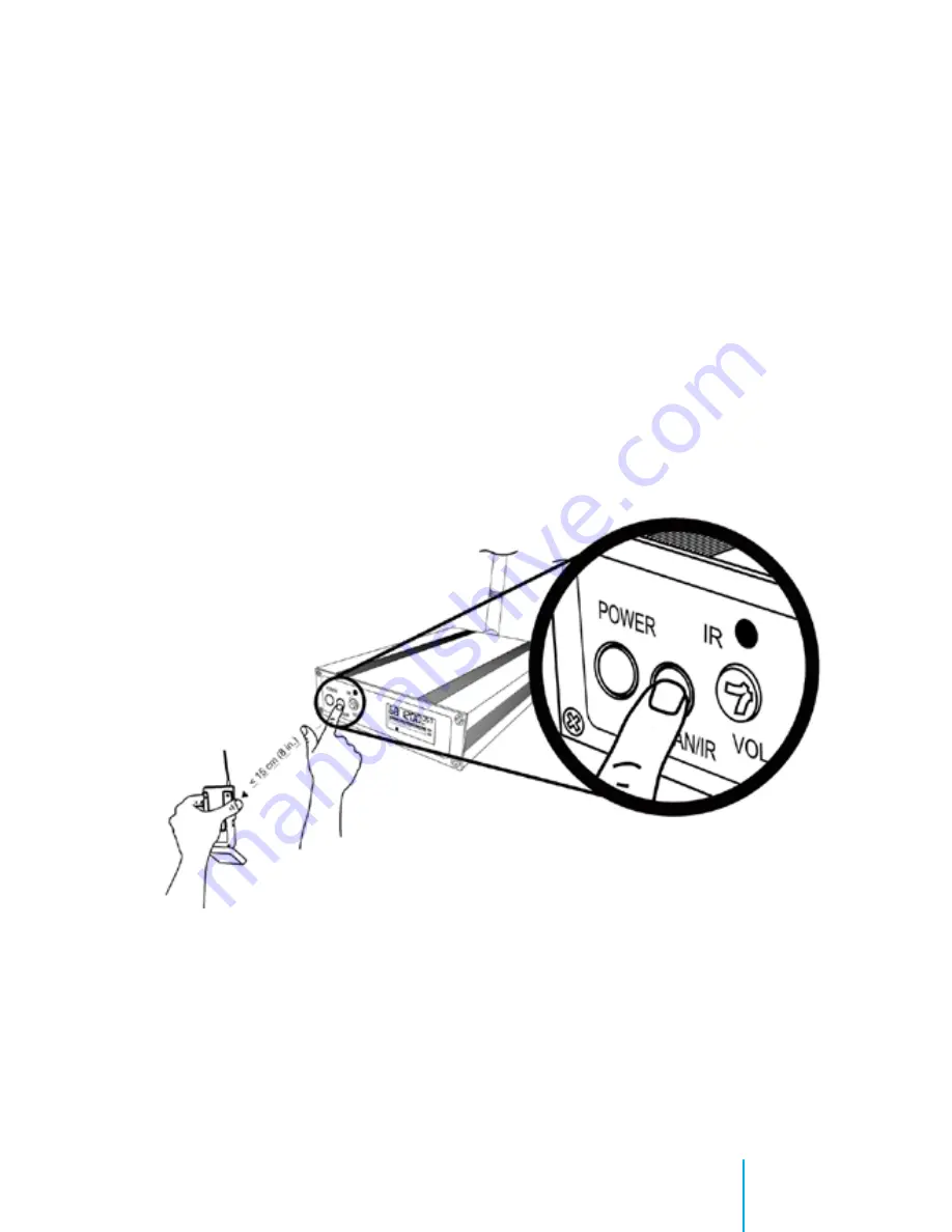
Expose the transmitter IR port to the receiver. (FIG. 6)

Press and hold the 

Scan/IR

 button on the receiver until the red light 

stops flashing on both the receiver and transmitter. (FIG. 6)


When the receiver’s 

ready light

 glows, the system is ready for use.

Close the transmitter’s battery compartment.

FIG. 6

Syncing the Transmitter and Receiver

Summary of Contents for In-Car Video System

Page 1: ...2013r2 Installation User Manual 10 8 In Car Video System...

Page 2: ...bility is assumed by 10 8 Video Digital Evidence Solutions for its use nor any infringements of patents or other rights of third parties resulting from its use No license is granted under any patents...

Page 3: ...request replacement parts via our website at http www 10 8video com warranty form php 2 We will then mail a new component via USPS Priority Mail within one 1 business day 3 When you receive the replac...

Page 4: ...16 Emergency Lights Manual Activation 18 2 4GHZ Wireless Mic 20 2 4 Ghz Wireless Mic DVR Set up 21 Black Wire Audio Out 21 2 4GHZ Mic Antenna 23 UHF Wireless Mic 24 Single System Setup 26 Automatic Fr...

Page 5: ...In Car Playback 42 Watch Previously Recorded Events 42 Viewing Today s Recordings 42 Viewing Another Day s Recordings 43 Stopping Playback 43 DVR Remote Control 44 Selecting Camera 44 Entering Your U...

Page 6: ...g Playback 55 Monitoring G Force and Speed Events 55 Using the Google GPS Window 56 Saving a Snapshot 56 Exporting Events to a Video File 57 Maintaining Evidence Integrity 57 Exported File Format 57 S...

Page 7: ...7 Contents This page left intentionally blank...

Page 8: ...8 CD ROM CD ROM...

Page 9: ...er software needed for playback on your computer It also includes PDF copies of all manuals Manuals To access the manuals 1 Insert the CD into your CD ROM DVD drive 2 When the installation program lau...

Page 10: ...afety Installation Safety WARNING This product utilizes high voltage Any unauthorized modifications or damage to the products may result in electrical shock 10 8 Video or its branches are not liable i...

Page 11: ...ocal traffic regulations 10 8 Video cannot accept any responsibility whatsoever for accidents resulting from failure to observe these precautions or safety instructions WARNING Do not use any features...

Page 12: ...ckage Contents Camera Mount Digital Video Recorder DVR Mirror Wireless Mic Optional 2 4GHZ model shown GPS Unit Optional REC ALM SD1 PWR GPS SD2 IR NOTE Actual camera appearance may vary from illustra...

Page 13: ...13 HARNESSES Simplified for clairity Power Harness Sensor Harness Mirror Harness Camera Harness A V Harness 2 4GHZ Harness Video Harness...

Page 14: ...4Mhz Mic to manual activation switch to pursuit lights Blue Wire of 2 4Mhz Mic Sensor 2 Out Sensor 1 Out Sensor 1 In Sensor 2 In Sensor 3 In 4 Pin A V Harness 6 Pin Power Harness CAT 5 GPS BLACK PWR...

Page 15: ...nputs in the picture on pages 12 and 13 You will need two 12 volt power sources a constant 12 volt power source and a switched 12 volt power source You will also need a ground source We strongly recom...

Page 16: ...avis consoles Havis offers a one piece mounting bracket Part C E T8V 1P For Jotto consoles Jotto offers a mounting bracket Part 425 6293 1 Insert the Red Black 6 pin Power Harness Connector into power...

Page 17: ...ound 4 Pin AV Harness GPS 6 Pin Power Harness Camera Harness Sensor Harness GPS FIG 1 Connecting Harnesses to DVR 1 4 5 6 7 Try to keep the unit in sight of the driver where they will be able to use t...

Page 18: ...recorder will start anytime you are running emergency traffic Depending on the type of switch box used there may be a place to connect at the back of the switch box If not simply connect to any wire...

Page 19: ...ctivation switch Sensor In 3 Green Wire to green wire of 2 4Ghz Mic FIG 2 Sensor Harness Caution These wires are very sensitive and care must be taken that you do not connect to a wire that has low vo...

Page 20: ...easily accessible position Be sure there is room to easily insert and remove the transmitter in the cradle 2 Connect the harness BLUE wire labeled 12v input rec to the DVR BLUE wire labeled Alarm out...

Page 21: ...f the setting as they are configured 6 Scroll down to Save and select to save the changes Default Password 111111 7 Go to the Alarm Out section 8 Activate Output 2 ensure it is set to High 9 Scroll do...

Page 22: ...Blue Wire Sensor 2 Out Blue Sensor 3 In Green CAT 5 BLACK PWR GND to ground RED PWR to Constant 12V Supply female RCA Audio Out male RCA to DVR CAM1 CAM PWR CAM signal FIG 3 2 4GHZ Wireless Mic Insta...

Page 23: ...the gold plug on the top of the cradle 2 Secure by tightening the lock nut 3 Run the wire down under the dash or other hidden location somewhere toward the front of the vehicle Velcro or double sided...

Page 24: ...ient for you It is recommended that it be in the front half of the vehicle for the best reception 2 Plug in the power lead to one of the available power leads on the DVR power harness 3 Attach the two...

Page 25: ...5 FIG 4 UHF Wireless Receiver FRONT 1 2 Power Button SCAN IR Press to synchronize transmitter and receiver frequencies 3 Volume Adjustment 4 Infrared IR Port Broadcasts IR signal to transmitter 5 LED...

Page 26: ...ency or channel The 10 8 wireless system uses automatic transmitter setup to synchronize the transmitter and receiver frequencies Automatic Frequency Selection 1 Press and release the Frequency button...

Page 27: ...ort See page 28 3 Expose the transmitter IR port to the receiver FIG 6 4 Press and hold the Scan IR button on the receiver until the red light stops flashing on both the receiver and transmitter FIG 6...

Page 28: ...stems only one transmitter IR port should be exposed at a time 5 Built in Wireless Mic Color State Meaning Green Solid Ready Green Flashing Controls locked Red Solid Battery power low Transmitter cann...

Page 29: ...he clip Expected life for alkaline batteries is approximately eight 8 hours When the transmitter light glows red the batteries should be replaced immediately as illustrated 2 1 Use of the external mic...

Page 30: ...3 Run the wires down along the door edge and under the glove box to the location of the DVR 4 Connect the power lead to one of the available power leads on the DVR power harness 5 Plug the yellow RCA...

Page 31: ...31 Mirror Installation FIG 8 Mirror Installation 4 Pin A V Harness to DVR Power Male Yellow RCA Female Power Female Video Female Video Male Yellow RCA Male...

Page 32: ...high and just right of center on the windshield 2 Clean the glass where the mount is to be placed 3 Press in on the center button of the mount and pull the locking lever up and over the center button...

Page 33: ...33 Camera Mount Installation 1 2 3 Press in button Pull lever over button Locked position...

Page 34: ...era to the BNC video in cable from the DVR 3 Connect the power lead to one of the available power leads on the DVR power harness 4 Adjust the large locking wheel FIG 10 above the camera so that the ca...

Page 35: ...era appearance may vary from illustration Front Camera Installation Power Female BNC Female BNC Male Power Male BNC Male Video Male RCA Female BNC Female TO DVR Power Female Power Male FIG 10 Front Ca...

Page 36: ...o features an integrated microphone to capture sounds and conversations in the interior of the vehicle Mounting options for this camera will vary greatly from vehicle to vehicle and will depend on typ...

Page 37: ...video is played The GPS Antennae can be mounted in or outside of the vehicle as long as it has a clear view of the sky As long as the vehicle is in a location with a clear view of the sky and GPS sat...

Page 38: ...htly right of center view This allows for a centered view of a vehicle during a traffic stop if you use a left offset during your stops The additional slot is for extra storage Each slot can accept a...

Page 39: ...lts username admin password 111111 This is the ID that will be displayed in recordings to identify which unit made the recording Up to 8 characters can be used here 2nd Camera Configuration If your de...

Page 40: ...d to change 6 Highlight the area to be changed and press OK button 7 Change values with keys and press OK again to accept 8 When everything is set for your location choose the Save button on the scree...

Page 41: ...periences an impact or jolt that is above the setting the sensor is set at It will continue to record for approximately 30 seconds after impact Along with the 30 second pre record of the recorder this...

Page 42: ...defaults to today s recordings 1 After the Playback screen loads select the Search button on the screen 2 Press the Enter remote button 3 A list of events that have been recorded starting with the lat...

Page 43: ...ack screen or use the search form to specify the day 2 Select the Search button on the screen and press the Enter remote button 3 A list of events that have been recorded starting with the latest at t...

Page 44: ...ng the 2 button will select the rear 2 camera in the view Entering Your Unit Car ID See Entering Your Information on page 39 FIG 12 DVR Remote DVR Remote Control Menu Up Left Right Down Return to Prev...

Page 45: ...to align the camera as needed This adjustment should only be tightened enough to hold the camera in place while driving but loose enough to allow the camera to be swivelled or moved as needed Adjustme...

Page 46: ...ynch 3 When the transmitter is ready for use the Talk light will flash briefly Transmitting Audio Pressing the red Talk button switches the unit between stand by and actively transmitting Hardware Usa...

Page 47: ...this is the only microphone you will need However the unit is also supplied with a wired lapel microphone Should this mic be needed simply plug the microphone into the top of the transmitter This wil...

Page 48: ...it on for the entire shift The audio will only record when the unit is activated but it will prevent you from missing critical audio when something comes up and you forget to turn it on If needed it c...

Page 49: ...e CD is not available you may download the player software from the 10 8 Video web site http www 10 8video com The player software will associate any files with the extension 264 with itself This will...

Page 50: ...he folder or files to review 6 Tabs Display Will show Files List or Events List depending upon which tab is selected 7 G Force Graph 8 Playback Speed 9 Playback Volume 10 Playback Timeline 11 Stop Pla...

Page 51: ...51 1 2 3 4 5 6 7 8 9 11 12 13 14 15 16 17 18 19 20 FIG 15 Software Player A B C 10 Software Overview...

Page 52: ...Microsoft Windows file dialog window will appear 4 Browse to the folder location of your file s 5 Click on the OK button 6 All of the available files in the selected folder will appear in the Tabs Dis...

Page 53: ...ll appear that allows you to narrow your search Path Define the physical location to search for files You can narrow your search to a specific computer drive Date Enter a specific date in the followin...

Page 54: ...eds range from 16 times slower to 16 times faster then normal speed Adjusting Playback Volume Use the Playback Volume Slider 3 FIG 16 to adjust the playback volume of the video file Maximizing the Vie...

Page 55: ...oring G Force and Speed Events The Event Monitor 7 FIG 16 will graph and display any changes in the vehicle s G Force along each axis X Y Z and the vehicle s speed in MPG KPH during the recording 2 3...

Page 56: ...ng the date and time along with the speed of the vehicle at the time of the recording Your computer must have access to the internet to use this feature as the map data is pulled from the Google serve...

Page 57: ...iginal format Exported File Format If you do not have a need to maintain evidence integrity you can export the videos into the standard AVI file format using the MP4 file compression codec Steps to Ex...

Page 58: ...progress bar that will display the overall progress of the exporting process Clicking the start button begins the export process Output Change Open Clicking the Change button will allow you to specify...

Page 59: ...page of a specific moment in a video recording You can generate as many of these reports as needed 1 Set the player to display the exact moment for which you want to generate a report 2 Click on the...

Page 60: ...ayed when the program opens Map Parameters Show GPS Track Enable the display of the path of the vehicle on the GPS map Video Parameters Watermark Verify Will determine video is original unedited Use R...

Page 61: ...l 264 video files on the computer to automatically open with the 10 8 Video Player Selecting this option is recommended AVI Checking this box will associate all AVI video files on the computer to auto...

Page 62: ...computer On many systems that can easily be done by holding down the key with the 4 little squares that look like the Windows logo and pressing the E key 3 Click on the drive letter that will store t...

Page 63: ...te the time frame of the video by the folder name Do not delete or format the SD card Just return it to the officer s vehicle and insert it back in the DVR It will still be at 10 but when it reaches 0...

Page 64: ...64 Appendix A GMT Time Zones United States Time Zone Name UTC GMT Offset Atlantic GMT 4 Eastern GMT 5 Central GMT 6 Mountain GMT 7 Pacific GMT 8 Alaska GMT 9 Hawaii Aleutian GMT 10...

Reviews: