background image

EES-1024AF Intelligent Ethernet Switch Optional Modules Guide 


Optional Modules                                                                                                     

                        3-3 

• 

128Kb memory buffer sharing 

• 

Supports store-and-forward switching 

• 

Supports half-duplex and full-duplex modes at 10/100 Mbps on MII interface 

• 

1000M, 100M, LK/ACT and FD/COL LEDs  

Front Panel LEDs 

There are four LEDs for the RJ-45 port. 

Table 3-2 EM1024A-GTP LED Description 

LED COLOR STATUS 

DESCRIPTION 

1000M 

Green 

On 

An Ethernet device is connected at 1000 Mbps. 


Off 

An Ethernet device is connected at 10 Mbps or is not connected.  

LK/ACT Green 

On 

Blinking 

Off 

The port is connected to an Ethernet device. 

The port is receiving or transmitting data. 

No Ethernet device is connected to this port.  

100M 

Green 

On 

An Ethernet device is connected at 100 Mbps. 


Off 

An Ethernet device is connected at 10 Mbps or is not connected. 

FD/COL Yellow 

On 

Blinking 

Off 

The port is operating in full-duplex mode.  

Collisions occurred. 

The port is operating in half-duplex mode. 

3.4 100Base-FX Fiber Intelligent Module Series        

3.4.1 

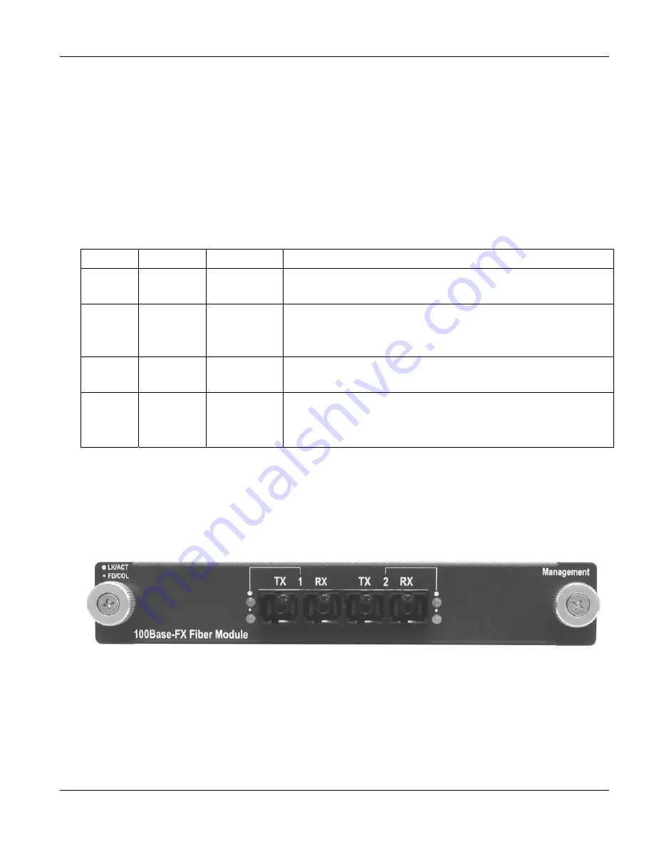
EM1024A-2FX-SC: 2-Port 100Base-FX (Multi-mode) 

Intelligent Fiber Module 


Figure 3-3 

EM1024A-2FX-SC 

Front Panel 

Содержание ZyXEL EES-1024AF

Страница 1: ...EES 1024AF Intelligent Ethernet Switch December 2002 User s Guide ...

Страница 2: ...sion of ZyXEL Communications Corporation Published by ZyXEL Communications Corporation All rights reserved Disclaimer ZyXEL does not assume any liability arising out of the application or use of any products or software described herein Neither does it convey any license under its patent rights nor the patents rights of others ZyXEL further reserves the right to make changes in any products descri...

Страница 3: ... damaged by an act of God or subjected to abnormal working conditions Note Repair or replacement as provided under this warranty is the exclusive remedy of the purchaser This warranty is in lieu of all other warranties express or implied including any implied warranty of merchantability or fitness for a particular use or purpose ZyXEL shall in no event be held liable for indirect or consequential ...

Страница 4: ...les These limits are designed to provide reasonable protection against harmful interference in a commercial environment This equipment generates uses and can radiate radio frequency energy and if not installed and used in accordance with the instruction manual may cause harmful interference to radio communications Operation of this equipment in a residential area is likely to cause harmful interfe...

Страница 5: ...E LOCATION SALES FAX FTP SITE REGULAR MAIL support zyxel com tw 886 3 578 3942 www zyxel com www europe zyxel com WORLDWIDE sales zyxel com tw 886 3 578 2439 ftp europe zyxel com ZyXEL Communications Corp 6 Innovation Road II Science Based Industrial Park Hsinchu 300 Taiwan support zyxel com 1 714 632 0882 800 255 4101 www zyxel com NORTH AMERICA sales zyxel com 1 714 632 0858 ftp zyxel com ZyXEL ...

Страница 6: ......

Страница 7: ...2 Rear Panel 2 2 2 2 Mounting the EES 1024AF 2 3 2 2 1 Desktop Mounting 2 3 2 2 2 Rack mounted Installation 2 4 Chapter 3 Optional Modules 3 1 3 1 Introduction 3 1 3 2 EM1024A 8TP 8 Port 10 100 auto sensing Intelligent Switch Module 3 1 3 3 EM1024A GTP Gigabit 1000Base T Intelligent Switch Module 3 2 3 4 100Base FX Fiber Intelligent Module Series 3 3 3 4 1 EM1024A 2FX SC 2 Port 100Base FX Multi mo...

Страница 8: ... 5 Internet Group Management Protocol IGMP 5 3 5 6 Setting the VLAN Mode 5 4 5 7 Setting the VLAN for CPU 5 4 5 8 Configure Secure IP Addresses 5 5 5 9 General Setup Complete 5 5 Chapter 6 Using the Web Configurator 6 1 6 1 Introduction 6 1 6 2 System Login 6 1 6 3 Navigating the Web Configurator 6 2 6 3 1 Task Bar 6 2 6 3 2 The Web Configurator Front Panel Display 6 2 6 3 3 Commonly Used Buttons ...

Страница 9: ...figuration and Firmware Maintenance 8 1 8 1 Save and Reboot 8 1 8 1 1 Save 8 1 8 1 2 Reboot 8 1 8 2 Reset to Factory Default Settings 8 1 8 3 Upgrade 8 2 Chapter 9 Troubleshooting 9 1 9 1 Console Port 9 1 9 2 Telnet 9 1 9 3 Web Configurator 9 1 Appendix A Microsoft Internet Explorer 5 0 Setup A Appendix B Product Specifications E Index I ...

Страница 10: ......

Страница 11: ...024A SX SC Front Panel 3 6 Figure 3 8 EM1024A LX SC Front Panel 3 6 Figure 3 9 Loosening the Screws and Removing the Cover Plate 3 7 Figure 3 10 Inserting the optional module 3 8 Figure 4 1 Connecting the Switch to a terminal via RS 232 cable 4 1 Figure 4 2 Parameter settings of communication parameters in Hyper Terminal 4 2 Figure 4 3 SMT Initial Screen 4 2 Figure 4 4 SMT Login 4 2 Figure 4 5 SMT...

Страница 12: ...7 Web Configurator Port Priority 802 1 7 9 Figure 7 8 Web Configurator Port Priority IPv4 Type of Service 7 10 Figure 7 9 Web Configurator IGMP 7 11 Figure 7 10 Web Configurator Static Address 7 12 Figure 7 11 Web Configurator Broadcast Storm Filter 7 13 Figure 7 12 Web Configurator Port Mirroring 7 14 Figure 7 13 Web Configurator IP Config 7 15 Figure 7 14 Web Configurator SNMP 7 16 Figure 8 1 We...

Страница 13: ... Main Menu Summary 4 3 Table 5 1 Port Settings Fields 5 1 Table 5 2 Fields in VLAN for CPU options 5 4 Table 5 3 Fields in Secure IP 5 5 Table 6 1 Web Configurator Front Panel LED Color Descriptions 6 2 Table 6 2 Commonly Used Buttons 6 3 Table 6 3 Home Page Field Description 6 4 Table 7 1 Port Management Field Description 7 1 Table 7 2 The Statistics Field Description 7 3 Table 7 3 VLAN Page Butt...

Страница 14: ......

Страница 15: ...E5 0 Add Trusted Site IP Address B Diagram 4 IE5 0 Security Settings B Diagram 5 IE5 0 Edit Permissions C Diagram 6 IE5 0 Internet Security Change Verification C Diagram 7 General Product Specifications E Diagram 8 Performance and Management Specifications F Diagram 9 Physical and Environmental Specifications G Diagram 10 Optional Modules Specifications H ...

Страница 16: ......

Страница 17: ...itoring you can visually configure and manage your network via the web browser General Syntax Conventions Enter means for you to type one or more characters and press the carriage return Select or Choose means for you to select one from the predefined choices The SMT menu titles and labels are in Bold Times font Predefined field choices are in Bold Arial font Command and arrow keys are enclosed in...

Страница 18: ......

Страница 19: ... This part acquaints you with the features and applications of the EES 1024AF Intelligent Ethernet Switch instructs you how to make the hardware connections understand the front panel LEDs and introduces the SMT System Management Terminal ...

Страница 20: ......

Страница 21: ... your mouse instead of typing cryptic command strings In addition the switch can also be managed via Telnet the console port or third party SNMP management 1 1 Features Conforms to IEEE 802 3 IEEE 802 3u IEEE802 3z IEEE 802 1d IEEE 802 1q and IEEE 802 3x 24 auto negotiating 10 100Mbps Ethernet RJ 45 ports 2 Expansion slots for optional module 1 port Gigabit SX LX 2 4 port 100Mbps Fiber SC ST MT RJ...

Страница 22: ... 4 Management Methods The switch supports the following management methods Console and Telnet Management Web configurator SNMP Network Management 1 4 1 Console and Telnet Management Managing the switch through the console port requires a direct connection between the computer and the switch using the RS 232 console port You can also telnet into the switch from any computer on your network provided...

Страница 23: ...telligent is used The switch provides versatile configuration options for the network It is ideally suited as a workgroup or segment switch in a network it has the flexibility to provide switched 10Mbps network link to the desktop or shared hubs aggregate traffic from workgroup switches or provide dedicated 100Mbps or 1000Mbps Gigabit to servers with bandwidth intensive applications Since all Fast...

Страница 24: ...n for bandwidth and eliminate server and network bottlenecks All ports can connect to high speed department servers that need high bandwidth The switch provides parallel communications within its Gigabit port which can run up to 2000 Mbps at full duplex mode The switch makes key servers available to more users by allowing multiple conversations to occur concurrently thereby significantly expanding...

Страница 25: ...ination of standard switches bridges and routers The bridges and routers quickly become bottlenecks reducing overall network throughput Switching to higher speed LANs such as FDDI or ATM is not a good choice for most people However such broadband equipment is still extremely expensive and difficult to maintain Besides you have to replace all existing Ethernet cable and adapter cards restructure yo...

Страница 26: ...cts to a segment that is a single broadcast domain Packets received in one VLAN can only be forwarded within that VLAN VLAN allows the logical grouping of end stations based not on physical location but on business policies such as job function or department Members of a group can be dispersed throughout a facility they do not have to be connected in close physical locations Hence group members ca...

Страница 27: ...ion Shared Server The switch s compliance to the IEEE802 1Q tagging VLAN standard allows ports to exist in multiple VLANs for shared resources such as servers printers or Switch to Switch connections It is also possible to have resources exist in multiple VLANs on one switch as shown in the following figure ...

Страница 28: ... to Know the EES 1024 Figure 1 5 Shared Server In this example stations in different VLANs share resources As a result VLAN 1 and VLAN 2 can access VLAN 3 for printing All VLAN port members of VLAN3 can see the broadcasts from ports configured in VLAN3 ...

Страница 29: ...MDIX Your switch comes with 24 10 100Mbps auto sensing ports for 10Base T or 100Base TX devices connections With the auto MDI MDIX feature you can connect to another switch or workstation without changing to straight through or crossover network cables Expansion Slots The chassis of the switch contains two expansion slots The optional modules come with the built in CPU module You can choose two of...

Страница 30: ...The system is turned on PWR Green OFF The system is off ON The system is functioning abnormally ALM Red OFF The system is functioning normally ON The link to a 100 Mbps Ethernet network is up 100 Green OFF No device attached or in 10Mbps mode ON The port is connected with a device Blinking The port is receiving or transmitting data LK ACT Green Off No device attached ON The port is operating in Fu...

Страница 31: ...ash red When the switch passes the self test within 15 seconds the Link ACT LED turns on If the switch fails the self test the ALM LED will blink 2 2 Mounting the EES 1024AF The switch is suitable for use in an office environment where it can be rack mounted in standard EIA 19 inch racks or standalone For proper ventilation allow about at least 4 inches 10 cm of clearance on the front and 3 4 inch...

Страница 32: ...2 2 2 Rack mounted Installation The EES 1024AF can be mounted on a 19 inch rack or in a wiring closet with other equipment Follow the steps below to mount your EES 1024AF on a 19 inch rack using the included rack mounting kit Step 1 Align one bracket with the holes on one side of the EES 1024AF and secure it with the bracket screws smaller than the rack mouting screws Similarly attach the other br...

Страница 33: ...EES 1024AF Intelligent Ethernet Switch Hardware Connections 2 5 Figure 2 6 Mount the switch in an EIA standard 19 inch Rack ...

Страница 34: ......

Страница 35: ...rt Gigabit 1000Base SX LX Fiber Intelligent modules 8 port 10 100 auto sensing Intelligent module 2 port 4 port 100Base FX Fiber Intelligent modules The following sections provide a brief description of each optional module 3 2 EM1024A 8TP 8 Port 10 100 auto sensing Intelligent Switch Module Figure 3 1 EM1024A 8TP Front Panel Features Eight 10 100Mbps Ethernet switch ports Supports auto MDI MDIX a...

Страница 36: ...vice is connected at 10Mbps LK ACT Green On The port is connected to an Ethernet device Blinking The port is transmitting or receiving data FD COL Yellow On The port is operating in full duplex mode Blinking Packet collision occurred on this port Off The port is operating in half duplex mode 3 3 EM1024A GTP Gigabit 1000Base T Intelligent Switch Module Figure 3 2 EM1024A GTP Front Panel Features Gi...

Страница 37: ...f An Ethernet device is connected at 10 Mbps or is not connected LK ACT Green On Blinking Off The port is connected to an Ethernet device The port is receiving or transmitting data No Ethernet device is connected to this port 100M Green On An Ethernet device is connected at 100 Mbps Off An Ethernet device is connected at 10 Mbps or is not connected FD COL Yellow On Blinking Off The port is operati...

Страница 38: ...wo Four 100Mbps fiber ports SC connectors 5MB memory buffer 12K entry MAC address table Supports store and forward switching Supports half duplex and full duplex modes LK ACT and FD COL LEDs Supports connection distance of up to 2 kilometers via fiber optic cable Supports SNMP management 3 4 3 EM1024A 2FX SC 30 2 Port 100Base FX Single mode Intelligent Fiber Module Figure 3 5 EM1024A 2FX SC 30 Fro...

Страница 39: ...ACT and FD COL LEDs Supports connection distance of up to 30 kilometers via fiber optic cable Supports SNMP management Front Panel LEDs There are two LED indicators for each fiber port Table 3 3 100Base FX Fiber Module Series LED Description LED COLOR STATUS DESCRIPTION LK ACT Green On The port is connected to an Ethernet device Blinking The port is transmitting or receiving data Off The port is n...

Страница 40: ...nnectors 4K MAC address table Supports store and forward switching LK ACT FD and COL LEDs Supports connection distance of up to 220 meters using 62 5 125um Multi mode fiber and up to 500 meters using 50 125um Multi mode fiber via fiber optic cable Supports SNMP management 3 5 2 EM1024A LX SC Gigabit 1000Base LX Intelligent Module Figure 3 8 EM1024A LX SC Front Panel Features One auto negotiating 1...

Страница 41: ...stall two optional modules separately to meet the needs of your network The procedure for installing the optional modules is the same Follow these steps to install the optional modules Step 1 Turn off your switch and unplug the power cord from the switch Step 2 Loosen the thumbscrews from the cover plate and remove the cover plate from the optional slot Do not discard the cover plate You can put t...

Страница 42: ...d or twist the optional modules into the expansion slots Step 6 Turn on the switch The switch automatically detects the installed optional module Connect any necessary network cables to the optional module and check the LEDs to verify that it is functioning properly Slide the optional module into the expansion slot until it snaps into place ...

Страница 43: ...ale DB 9 connector to connect to a computer or terminal for monitoring and configuring the switch Use the supplied RS 232 cable with a female DB 9 connector to connect a terminal or computer to the Console port Figure 4 1 Connecting the Switch to a terminal via RS 232 cable 4 2 Establishing the Console Port Connection After the switch is connected to a computer turn on the computer and run a termi...

Страница 44: ...Control flow None 4 2 1 Initial Screen At the prompt type go and press ENTER to display the main screen as shown next Figure 4 3 SMT Initial Screen 4 2 2 Password Screen optional If you enabled the console password login option the following screen displays To disable or enable this option see 4 4 2 Enable Console Login Figure 4 4 SMT Login Type go to enter main menu go Login root Password User ro...

Страница 45: ... ENTER Save your configuration ENTER Save your configuration by pressing ENTER at the message Press ENTER to confirm or ESC to cancel Saving the data on the screen will take you in most cases to the previous menu Exit the SMT Type q or Q then press ENTER Type q or Q at the main menu prompt and press ENTER to exit the SMT interface 4 3 1 The Main Menu After you log in the SMT displays the Main Menu...

Страница 46: ...R Reboot System This option reboots the system and makes all new settings take effect Q Quit To exit the SMT menu you must type q or Q The SMT is not case sensitive therefore you can type either q or Q at the prompt to exit 4 4 Device Settings 4 4 1 Changing Your System Password It is important to change the system password or login name by doing the following Step 1 Enter 1 from the main menu Thi...

Страница 47: ...1 1 Step 3 Enter 5 to select Subnet Mask and enter the subnet mask IP Net mask address Default subnet Mask is 255 255 255 0 Step 4 Enter 6 to Select Default Gateway and enter the IP address of the default gateway if you are sending packets to another IP network Default Gateway is 192 168 16 254 The gateway address is the router that can forward packets to the other IP networks Return to the main m...

Страница 48: ...ompts you to log in again Figure 4 8 SMT Reboot System 4 6 Resetting the EES 1024AF You can reset the switch to the factory default values All your custom configurations will be lost except the IP address of the switch Step 1 Enter d from the main menu Step 2 Enter y to continue the reset process Otherwise enter n to returnt to the main menu Step 3 Wait for a moment while the switch reboots and pr...

Страница 49: ...Getting Started II Part II Getting Started This part shows you how to configure the basic setup using the SMT menus and introduces you to the Web Configurator ...

Страница 50: ......

Страница 51: ...t this option to enable or disable the port Enabled 2 Speed Duplex Set the port speed and duplex mode with this option The switch will auto detect the speed and duplex mode of the attached device if you select Auto otherwise check the settings of the device attached to this port and select from the following 100 Full 100 Half 10 Full and 10 Half Auto 3 Flow Control When this option is enabled the ...

Страница 52: ...cific port in Address Table Follow the steps to view all your port information Step 1 Enter 3 from the main menu the to bring up the Address Table menu Step 2 Enter 1 and press ENTER to display information on all ports currently connected to the switch Figure 5 2 SMT Address Table All You can also select options 1 and 2 to display port information on a specific module 5 3 Spanning Tree Protocol ST...

Страница 53: ...oadcast Storm Filter 5 5 Internet Group Management Protocol IGMP Follow the steps to enable or disable the IGMP Step 1 Enter 6 from the main menu to open IGMP page Step 2 Enter 1 to enable or 2 to disable the IGMP Main Spanning Tree Protocol Current state Enabled 1 Enable 2 Disable 3 Show Port State Q Quit Select one function 1 3 Q 3 Main Spanning Tree Protocol Show Port State Module Port State 0 ...

Страница 54: ... first VLAN for CPU Select this option and enter the VLAN ID for the first CPU You can choose from ID 1 to 4095 1 2 Current second VLAN for CPU Select this option and enter the VLAN ID for the second CPU You can choose from ID 1 to 4095 None Press q to exit this menu Main IGMP Current state Enabled 1 Enable 2 Disable Q Quit Select one function 1 2 Q Main VLAN Mode Current mode 1 1 VLAN is valid fo...

Страница 55: ... the Secure IP screen Figure 5 8 SMT Secure IP Table 5 3 Fields in Secure IP FIELD DESCRIPTION EXAMPLE 1 Secure IP for Telnet Select this option and enable or disable the secure IP for Telnet sessions Enabled 2 Secure IP for HTTP Select this option and enable or disable the secure IP for HTTP sessions Enabled 3 6 Secure IP 1 4 Select these options to specify secure IP address es 192 168 1 10 Press...

Страница 56: ......

Страница 57: ...does not allow Java Applets to open sockets The user has to explicitly modify the browser setting to enable Java Applets to use network ports See Appendix A Microsoft Internet Explorer Setup You don t need to change any configuration if you use Netscape browser However Netscape browser doesn t support TFTP firmware upgrade 6 2 System Login Disconnect the Console port connection before launching th...

Страница 58: ...front panel of your switch at the top of every web page The front panel shows the modules installed in the switch and the link status of all ports The link status information is updated each time the Web Configurator polls the switch The colors of the LED indicate the operating status of the port Table 6 1 Web Configurator Front Panel LED Color Descriptions COLOR LINK STATUS Orange The port is ope...

Страница 59: ...s related to the buttons display at the bottom of the web pages Table 6 2 Commonly Used Buttons BUTTON FUNCTION Click this button to apply your new settings to the current runny configuration The new configuration will not take effect until you save and reboot your switch See 8 1Save and Reboot Click this button to clear the information you have just entered The procedure works only if you have no...

Страница 60: ...ime since the managed unit was re initialized IP Address The IP Address of the managed unit 192 168 1 1 Subnet Mask The subnet mask of the managed unit Default Gateway The default outgoing gateway of the managed unit Note You can change the IP Address Subnet Mask and Default Gateway field in the IP Config page Console Shows the RS 232 console settings of the switch the speed parity data bits and t...

Страница 61: ...bit 1000Base SX Fiber Module is installed into the switch Figure 6 5 Web Configurator Modules Any two of the following modules can be installed to the switch See the Optional Modules chapter for more information 8 port auto sensing 10 100Base TX Switch Module 2 port 100Base FX SC ST Fiber Module 4 port 100Base FX SC ST Fiber Module 2 port 100Base FX MT RJ VF 45 Fiber Module 4 port 100Base FX MT RJ...

Страница 62: ......

Страница 63: ...Advanced Applications and Management III Part III Advanced Applications and Management This part shows you how to use the advanced features of the Web Configurator ...

Страница 64: ......

Страница 65: ...ule This value shows the module number 0 1 or 2 Port Number This shows the number of the port in the module Enabled Select this option to enable a specific port Link Indicates whether a node links to that port is up or not Speed Duplex Set the transmission speed and the duplex mode in this field The switch will automatically detect the speed and the duplex mode of the attached device if you select...

Страница 66: ...ect this option to tag the VLAN ID to the packets transmitted through the specified port Default VLAN ID If a packet is received without the VLAN tagged then the Default VLAN ID is used to classify this packet to that VLAN Note Memorial note for this port max length is 16 characters IF you want to set multiple VLANs we suggest that you set Default VLAN ID for each port first then set VLAN in the V...

Страница 67: ...et with size of 65 to 127 bytes 128 255 Bytes This counter is incremented once for every received and transmitted packet with size of 128 to 255 bytes 256 511 Bytes This counter is incremented once for every received and transmitted packet with size of 256 to 511 bytes 512 1023 Bytes This counter is incremented once for every received and transmitted packet with size of 512 to 1023 bytes 1024 1536...

Страница 68: ...default VLAN id of the input port is used You can assign a single switch port to two or more VLANs The factory default VLAN is that all ports belong to the same VLAN group 1 VLAN also enable you to configure tag based VLANs to help isolate broadcast traffic and increase security Creating VLANs increases network flexibility by allowing you to reassign devices to accommodate network moves additions ...

Страница 69: ...ch port first in Ports page 7 4 Trunk Port trunking is the ability to group several 10 100Base TX or 100Base FX ports to increase the bandwidth between this switch and another compatible switch This is an inexpensive way to increase bandwidth We define port trunking as the ability to group sets of ports up to 8 within the same module into a single logical link The port trunk acts as a single link ...

Страница 70: ...only one active path must exist between two stations The spanning tree algorithm calculates the best loop free path throughout a switched network STP forces redundant data paths into a standby blocked state If a network segment in the spanning tree fails and a redundant path exists the spanning tree algorithm recalculates the spanning tree topology and activates the standby path Figure 7 5 Web Con...

Страница 71: ...rmation received on a port is stored by the root switch the default value is 20 Hello Time How often the root switch broadcasts Hello message to other switches the default value is 2 Forward Delay The amount of time a port will remain in the listening and learning states before entering the forwarding state the default value is 15 The Port Configuration describes those ports information in this sw...

Страница 72: ...from one to 127 in the Max Allowed MAC Address Count Per Port field to set the maximum MAC address for all ports Figure 7 6 Web Configurator Port Security To restrict the number of MAC address of a port you must do the following Step 2 Select Enable for that port If the Enable checkbox is not selected there is no MAC address count restriction for that port Step 3 Type the number in the Max Allowed...

Страница 73: ...h priority queue when the 802 1p user priority tag is 4 to 7 and to low priority queue when the 802 1p user priority tag is 0 to 3 Check the corresponding mapping checkbox to assign a high priority or uncheck that to assign a low priority Figure 7 7 Web Configurator Port Priority 802 1 7 8 Port Priority Type of Service Each port can parse the header of an incoming IPv4 header and identify the Type...

Страница 74: ...uery for any attached hosts who want to receive a specific multicast service The switch looks up the IP Multicast Group used for this service and adds any port which received a similar request to that group It then propagates the service request on to any neighboring multicast switch to ensure that it will continue to receive the multicast service If you want your switch to support multimedia and ...

Страница 75: ...r port Static addresses are manually entered into the Static Address Table Step 1 Enter the MAC address in the MAC Address field ex 00 00 00 00 00 01 and VLAN ID default is 1 Step 2 Select the Module and Port you want to associate with this entry with from the Port drop down box Step 3 Click Add and then the Apply button Remove the entry from current static address table to unlock a MAC address fr...

Страница 76: ...t Storms can be filtered out by enabling the Broadcast Storm Filtering option When this option is enabled if more than 3000 packets per second broadcast packets were sent to a port for 5 seconds the port will not receive any broadcast packets until less than 3000 packets per second broadcast packets were received for 5 seconds If a broadcast storm happens to a port you will see a red BS text appea...

Страница 77: ...t interrupting the flow of data across the network If you want to monitor all received and transmitted packets of a specific port follow the steps below Step 1 Select the monitored port from the Mirror Source Port drop down list in the corresponding Mirror Source Module Only one port can be monitored in one module at the same time Step 2 Select the corresponding target module port in Mirror Target...

Страница 78: ...er the IP address subnet mask and default gateway in the corresponding fields Follow the steps below if you want to change the user name or password for the managed node Step 1 Select Change Password Step 2 Enter the user name in the Username field Step 3 Enter the same password in the Password and Confirm Password fields Step 4 Click Apply Reboot the switch to make your settings take effect if yo...

Страница 79: ...Request Community to authorize management access For security you should change them to prevent unauthorized access Get Request Community Read only access right means that member of community can view the information but can not make changes to the configuration Set Request Community Read Write access right allow the member of the community to view and make change to the configuration To set the G...

Страница 80: ...EES 1024AF Intelligent Ethernet Switch 7 16 Advanced Web Management Figure 7 14 Web Configurator SNMP ...

Страница 81: ...current settings will take effect 8 1 2 Reboot If you want to reboot the switch select Reboot System then click Apply next to the checkbox Wait for about 30 seconds before you continue to use the Web Configurator 8 2 Reset to Factory Default Settings If you want to use the factory default settings select Factory Default Settings then click Apply next to the checkbox You should reboot the system so...

Страница 82: ...naged unit using the Web Configurator Step 1 Download the latest firmware from ZyXEL website http www zyxel com Step 2 Enter the password in the Password field Step 3 Enter the file downloaded in the File Path edit box Or click Browse to select the file Step 4 Click Upgrade After you have successfully upgraded to the new firmware reboot the system so that the new firmware will take effect ...

Страница 83: ...onfiguration and Firmware Maintenance 8 3 Figure 8 2 Web Configurator Upgrade Do NOT shut down the switch if you can t upgrade your new firmware successfully Try the upgrade process again Contact local customer support if any problem occurred ...

Страница 84: ......

Страница 85: ...Additional Information IV Part IV Additional Information This part contains the troubleshooting the appendices and the index ...

Страница 86: ......

Страница 87: ...s of the switch 2 Ping the switch from your computer If you cannot ping the switch check the IP addresses in the switch and your computer Make sure that both IP addresses are in the same subnet 3 If these steps fail to correct the problem contact the distributor 9 3 Web Configurator I cannot access the Web Configurator Table 9 3 Troubleshooting Web Configurator STEPS CORRECTIVE ACTION 1 Make sure ...

Страница 88: ...eshooting Internet Explorer STEPS CORRECTIVE ACTION 1 Make sure you are using Internet Explorer 4 0 or Netscape Communicator 4 x and later versions 2 Make sure the Java applet feature is turned on See the appendix on Windows Internet Explorer Setup to configure your Internet Explorer If you have Netscape web browser installed use it instead ...

Страница 89: ...in Internet Explorer follow the steps below to enable the Java applet security option Step 5 From Internet Explorer click Tools and then Internet Options Diagram 1 Internet Explorer 5 0 Step 6 Select the Security tab in the Internet Options window Then click Trusted Sites Diagram 2 IE5 0 Internet Options Step 7 Click Sites and type the IP address of the switch with the prefix https For example htt...

Страница 90: ...indow click Custom Level Step 9 Scroll down to the Microsoft VM option Under Java Permissions select Custom Then click the Java Custom Settings button that displays Diagram 4 IE5 0 Security Settings Step 10 Click the Edit Permission tab in the Trusted Sites window that displays Step 11 Select Enable under the Run Unsigned Content option Then click OK ...

Страница 91: ...rnet Switch Microsoft Internet Explorer Setup C Diagram 5 IE5 0 Edit Permissions Step 12 Click Yes to change the security settings then click OK to close all settings windows Diagram 6 IE5 0 Internet Security Change Verification ...

Страница 92: ......

Страница 93: ...ts Modules support for 10 100 100BaseT 100FX Gigabit SX LX One RS 232C console port Data Transfer Rate Ethernet 10Mbps half duplex 20Mbps full duplex Fast Ethernet 100Mbps half duplex 200Mbps full duplex Gigabit Ethernet 2000Mbps full duplex Available on optional Gigabit Module Network Cables 10BASE T 2 pair UTP Cat 3 4 5 100 m EIA TIA 586 100 ohm STP 100 m 100BASE TX 1000BASE T UTP Cat 5 100 m ma...

Страница 94: ...witch Data Buffer Main switch 4KByte excluding optional modules 8 ports 100BASE TX Module 256KByte 2 4 8 ports Fiber Module 4MByte Gigabit Module 128KByte VLAN IEEE 802 1Q tag based VLAN 4095 Max IEEE 802 1p Priority Queues 2 queues Port Trunking IEEE802 3ad port trunking 3 groups each group up to 8 ports Port Security Static MAC address filtering MAC address number limitation Multicasting Support...

Страница 95: ...e Full duplex Collision 100FX Fiber module 2 4 8 ports Link Active Full duplex Collision Gigabit Module Link Active Full duplex Collision Dimensions Main switch 441 W x 226 D x 66 5 H mm 17 3 W x 8 9 D x 2 6 H inches 19 inch rack mount width 1 5 U height Optional Switch Modules 178 W x 152 D x 25 H 7 W x 6 D x 1 H inches Power Supply 100 240VAC 50 60Hz internal universal power supply Power Consump...

Страница 96: ...X module EM1024A 2FX SC 2 x 100FX SC multi mode 2km EM1024A 2FX SC 30 2 x 100FX SC single mode 30km EM1024A 4FX SC 4 x 100FX SC multi mode 2km EM1024A 4FX SC 30 4 x 100FX SC single mode 30km Gigabit module EM1024A SX SC 1000Base SX SC multi mode Module Depends on fiber type EM1024A LX SC 1000Base LX SC single mode Module 10km EM1024A GTP 1000Base T UTP STP RJ 45 Module 100m on CAT5e ...

Страница 97: ...oint Duplex 5 1 E EMI G Enable Console Login 4 5 Ethernet Port Back Pressure 5 1 Flow Control 5 1 SMT Settings 5 1 Expansion Slots 2 1 F FCC iv FCC Rules iv Features 1 1 Firmware Maintenance 8 1 Firmware Version 6 4 Fragment 7 3 Front Panel 2 1 LED Descriptions 2 2 Web Configurator Display 6 2 G gateway address 4 5 Get Request Community 7 15 H Hardware Description 2 1 I IGMP See Internet Group Man...

Страница 98: ...ort Priority 802 1p 7 9 Type of Service 7 9 Port Security 7 8 Port Statistics 7 2 Power Consumption G Power Supply G Product Specifications E R Rear Panel 2 2 Reboot 4 6 Related Documentation xvii repair iii Resetting 4 6 8 1 RJ 45 ports 2 1 Root Hello Time 7 7 Root Max Age 7 7 RS 232 cable 2 2 S Save 4 5 Secure IP Addresses Configure 5 5 Service iii Set Request Community 7 15 SMT Main Menu Summar...

Страница 99: ...figurator 9 1 Trunk 7 5 Type Of Service 7 9 U Undersize 7 3 Upgrade 8 2 V ventilation 2 3 ventilation fan 2 2 Viewing Basic System Information 6 3 Virtual LAN See VLAN VLAN 7 4 VLAN for CPU 5 4 Mode 5 4 W Web Configurator 6 1 Home 6 4 Login 6 1 Modules 6 5 Navigating 6 2 Reset 8 1 Save and Reboot 8 1 Z ZyXEL Limited Warranty iii Note iii ZyXEL Web Site xvii ...

Отзывы: