background image

12

Quick change system for SPRINT Series

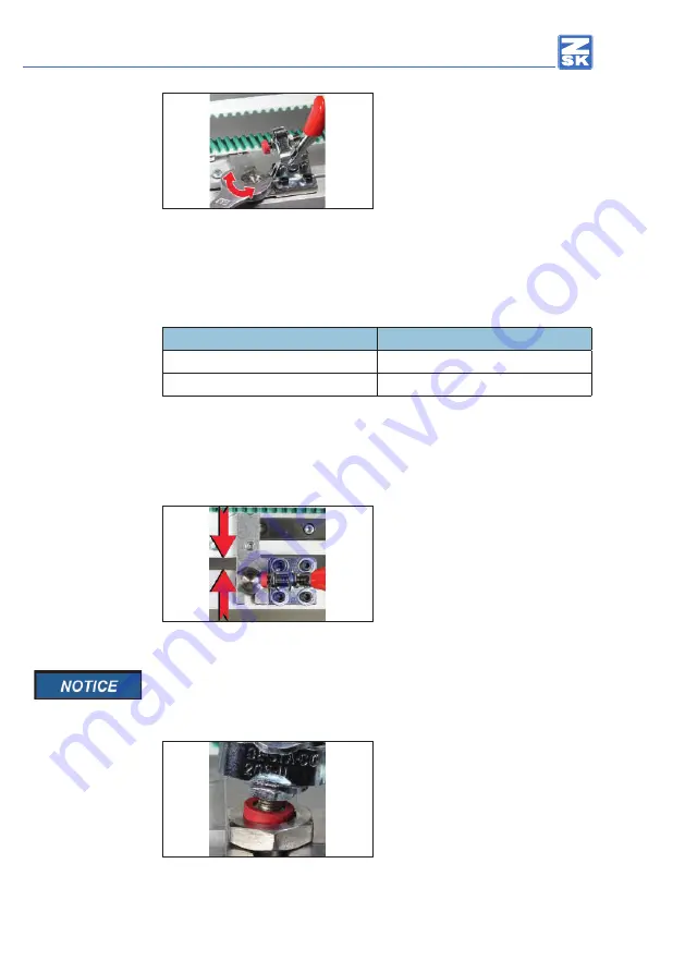
Using a suitable spanner set the 

absorving energy of the system with 

which the tubular frame has to be 

pushed in the guides on the centring 

devices. 

Fig. 20: Centring device, force setting

Check the setting by moving back and forth the cylinder arm frame holder  

Change and check the settings of the absorving energy until you find the 

appropriate setting. 

Centring device

Impact

Setting tighter

higher effort

Setting looser

smaller effort

The setting is right if the cylinder arm frame holder slides into both clevises 

evenly under slight pressure.

Slide the cylinder arm frame holder 

with the centring devices in the guides 

of the two clevises.

Set a 

parallel

 distance of 6,0 mm 

±0,3 between the carriages of the 

pantograph drive and the cylinder arm 

frame holder.

Fig. 21: Distance setting

To facilitate the setting of the 6 mm distance a correspondingly thick 

gauge can be applied. This can be a metal strip, 2 screws or similar 

material of the appropriate strength.

Place the clamping screws of the two 

horizontal clamping fixtures centered 

in the recording of centering devices.


Fig. 22: Clamping screw in the centring device

Содержание SPRINT Series

Страница 1: ...Quick change system SPRINT installation guide Made in Germany ZSK Stickmaschinen Made in Germany...

Страница 2: ......

Страница 3: ...ting the machine to the quick change system accesories which have not been converted can be connected as customary to the quick change system The quick change system is designed solely for machines of...

Страница 4: ...it quick fastener SPRINT 360 998 901 2 Clevis 360 010 207 2 Horizontal barrel adjuster 205 U 574 103 8 Cylinder head screw M3 x 6 DIN 912 307 002 8 Washer B 3 2 DIN 9021 380 013 4 Countersunk screw M4...

Страница 5: ...e screw head Slide one of the guide washers on the screw The guides of the washer should be located on the far side of the head of the clamping screw Carry out the assembly with the second clamping sc...

Страница 6: ...ure Fig 3 Clamping fixture adaptor side view Attach one of the pre installed horizontal clamping fixtures with 4 screws and 4 washers on one of the cleviss as shown in Fig 4 Thereby tightening the scr...

Страница 7: ...emove the cover of the pantograph drive for lateral movement Remove 2 screws with plastic washers on the top and the 3 screws with plastic washers on the back of the cover Do not loosen in any case th...

Страница 8: ...s from the two movable pilot carriages and remove the carriage Fig 10 Carriage view from the bottom The countersunk screws are inserted with LOCTITE 290 and they are sitting thightly Be careful when r...

Страница 9: ...crews securing the individual clevises firmly after both countersunk head of the screws are sitting in the intended cuts Fig 12 Carriage assembly Assemble the carriage with the 8 mounting screws incl...

Страница 10: ...n arrow evenly and dexter and align flush with the clevis Tighten the fastening screws firmly Fig 14 Clamping fixture right side adjustment Horizontal clamping fixture left side Distribute the horizon...

Страница 11: ...two centring devices Fig 17 Centring device and thrust washer Place a drop of Loctite 290 or equivalent adhesive from another manufacturer on the threads of the two centring devices Screw the two cent...

Страница 12: ...e setting is right if the cylinder arm frame holder slides into both clevises evenly under slight pressure Slide the cylinder arm frame holder with the centring devices in the guides of the two clevis...

Страница 13: ...ontal clamping fixtures are correctly adjusted when they can be completely closed with a clear click sound and not much effort Contact pressure Impact to small no click sound correct clear click sound...

Страница 14: ...u must adjust the settings of the pantograph within the T8 Software again Load an embroidery pattern in the machine While loading the pattern you will be asked to adjust the settings of the pantograph...

Страница 15: ...r until it stops on the threads of the two centring devices Fig 27 Centring device and thrust washer Place a drop of Loctite 290 or equivalent adhesive from another manufacturer on the threads of the...

Страница 16: ...rt The setting is right if the cap attachment slides into both clevises evenly under slight pressure A new adjustment of the clamping screws on the horizontal clamping fixtures is not necessary Fig 31...

Страница 17: ...ing fixtures Close the lower clampin device of the cap attachment by tightening the two wing bolts of the clamping device Fig 32 Cap attachment clamping device on the bottom The cap attachment can be...

Страница 18: ...you have to adjust the settings of the pantograph within the T8 Software Load an embroidery pattern in the machine While doing so you will be asked to adjust the settings of the pantograph Choose the...

Страница 19: ...washer until it stops on the threads of the two centerings Fig 36 Centring device and thrust washer Place a drop of Loctite 290 or equivalent adhesive from another manufacturer on the threads of the...

Страница 20: ...the border frame Change and check the setting of the absorving energy until you find the appropriate setting Centring device Impact Setting tighter higher effort Setting looser smaller effort The sett...

Страница 21: ...other operation mode you have to adjust the settings of the pantograph within the T8 Software Load an embroidery design in the machine You will be asked to adjust the settings of the pantograph Select...

Страница 22: ...22 Quick change system for SPRINT Series...

Страница 23: ...23 Quick change system for SPRINT Series...

Страница 24: ...ZSK Stickmaschinen GmbH Subject to change nderungen vorbehalten ZSK Stickmaschinen GmbH 2015 Printed in Germany GB 02396T10 Version 1 0 08 04 2015 DC...

Отзывы: