background image

42


GeForce6100-Value motherboard 

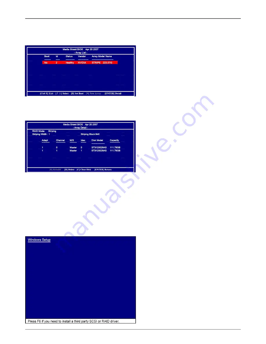
7. After that, then Array List screen displaying the RAID array you created will appear.

If you want to set the disk array as boot device, use the UP or DOWN ARROW 

key to select the array and press B. The Boot section will show Yes.

8. To read more information about the RAID array, press ENTER to enter the 

Array  Detail  screen,  where  you  should  see  detailed  information  about  

RAID mode, disk block size, disk model name, and disk capacity, etc.

9. To delete the array, press D in the Array Detail screen. When the “Delete this 

array?”  message  appears,  press Y  to  confirm  or  N  to  cancel.  Press  ENTER  to 

return  to  the Array  List  screen. To  exit  the  Nvidia  RAID  utility,press  ESC  in  the 

main menu or Ctrl+X in the Array List screen. Now, you can proceed to install the 

SATA controller driver and operating system.

Installing the RAID Drivers

1. After you complete the RAID BIOS setup, boot from the windowsXP CD. The 

Windows Setup program starts.

Содержание GeForce 6100-ITX series

Страница 1: ......

Страница 2: ... CONNECT THE EQUIPMENT INTO AN OUTLET ON A CIRCUIT DIFFERENT FROM THAT OF THE RECEIVER CONSULT THE DEALER OR AN EXPERIENCED AUDIO TELEVISION TECHNICIAN NOTE Connecting this device to peripheral devices that do not comply with Class B requirements or using an unshielded peripheral data cable could also result in harmful interference to radio or television reception The user is cautioned that any ch...

Страница 3: ...witches 12 20 pin ATX Power ATXPWR 13 4 pin ATX 12V Power 12VPWR 14 Speaker Connector SPEAKER 14 Connecting Serial ATA Cables 15 Front Panel Header 16 USB Headers Optional 17 FP Audio Connector 18 SPDIF Out Header Optional 19 Serial Port Connector COM Optional 19 Fan Connections 20 Expansion Slots 21 Jumper Settings 22 Configuring the BIOS 23 About the Setup Utility 23 Main Menu 24 Flash Update Pr...

Страница 4: ...Audio I O 35 Speaker Configuration 36 Connector Settings 36 S PDIF 37 Speaker Calibration 37 Microphone 38 Noise Suppression 38 Beam Forming 38 Acoustic Echo Cancellation 38 Audio Demo 39 Information 39 SATA RAID User Manual 40 Setting up the BIOS 40 Entering the RAID BIOS Setup 41 Installing the RAID Drives 42 Table of Contents ...

Страница 5: ...ports four rear panel ports six from three onboard USB headers Optional v Supports wake up from S1 S3 v Supports USB 2 0 protocol up to 480 Mbps transmission rate q Onboard Serial ATA II v Independent DMA operation on four ports Optional v Data transfer rates of 300 Mb s q Onboard LAN v LAN interface built in onboard v Supports 10 100 1000 Mbps Ethernet Optional q Onboard Audio Optional v Azalia H...

Страница 6: ...wer on the system v AC power failure recovery q Onboard Graphics Support v Integrates GeForce 6100 engine core v Supports DirectX9 0 Pixel Shader 3 0 q Expansion Slots v One PCI Express x1 slot Motherboard Specifications ...

Страница 7: ...peaker connector 9 PCI Express x1 slot 10 SPDIF Out Header Optional 11 Front pannel audio Connector 12 J2 BIOS selection jumper 13 USB Header 14 SYS Fan connector 15 Backpanel connectors 16 JPUSB USB power selection jumper 17 4 pinATX_12V power connector 18 CPU Socket 19 DDRII slots Socket AM2 Chipset DIMM1 DIMM2 ATXPWR SATA1 SATA2 _ USB USB LAN 2 3 4 5 6 7 8 9 10 12 13 14 15 16 17 18 VGA 19 SATA3...

Страница 8: ... Speaker Out Green Line Out Front Speaker Out Front Speaker Out Pink Mic In Mic In Center Subwoofer 6 Lan Port with LEDs to indicate status Red Light Up Blink 10 100 1000 Mbps Link Activity Orange Light Up Blink 10 100 1000 Mbps Transmit Receive Figure 2 Backpanel connectors With 6 Channel audio output Rear Panel 6 11 5 10 15 2 3 4 5 6 ...

Страница 9: ...ry always follow basic safety precations Remember to remove power from your computer by disconnecting the AC main source before removing or installing any equipment from to the computer chassis Preparing the Motherboard The motherboard shipped in the box does not contain a CPU and memory You need to purchase these to complete this installation Installing the CPU Be very careful when handling the C...

Страница 10: ...ot be seen Please note that any deviation from the correct installation procedures may cause permanent damage to your motherboard 4 Press the CPU down firmly into the socket and close the lever As the CPU is likely to move while the lever is being closed always close the lever with your fingers pressing tightly on top of the CPU to make sure the CPU is properly and completely seated in the socket ...

Страница 11: ... your chassis type and your fan assembly Installing Memory DIMMs Your new motherboard has two 1 8V 240 pin slots for DDR2 These slots support 256 MB 512 MB 1GB 2GB and 4 GB DDR2 There must be at least one memory bank populated to ensure normal operation Use the following the recommendations for installing memory See Figure 1 on page 6 for the location of the memory slots q One DIMM You can install...

Страница 12: ...make all the connections prior to this step or to secure the motherboard and then make all the connections It is normally easier to secure the motherboard first Use the following procedure to install the I O shield and secure the motherboard into the chassis Note Be sure that the CPU fan assembly has enough clearance for the chassis covers to lock into place and for the expansion cards Also make s...

Страница 13: ...ard Connecting Cables and Setting Switches This section takes you through all the connections and switch settings necessary on the motherboard See Figure 1 to locate the connectors and jumpers referenced in the following procedure ...

Страница 14: ...13 GND 4 5V 14 PS_ON 5 GND 15 GND 6 5V 16 GND 7 GND 17 GND 8 PWROK 18 5V 9 5V_AUX 19 5V 10 12V 20 5V ATXPWR 20 pin ATX Power ATXPWR ATXPWR is the main power supply connector Make sure that the power supply cable and pins are properly aligned with the connector on the motherboard Firmly plug the power supply cable into the connector and make sure it is secure ...

Страница 15: ...ction is used to provide power to the CPU Align the pins to the connector and press firmly until seated PIN Assignment 1 VCC 2 NC 3 NC 4 SPK SPEAKER Pin Definition 1 PIN Assignment 1 GND 2 GND 3 12V 4 12V 12VPWR Pin Definition Speaker Connector SPEAKER 120 240 121 120 240 121 Socket AM2 Chipset 2 3 4 12VPWR ...

Страница 16: ...connectorisusedtoconnecttheSerial ATAIIdevicetothe motherboard These connectors support the thin Serial ATA II cables for primary storage devices The current Serial ATA II interface allows up to 3Gb s data transfer rate There are four serial ATA connectors on the motherboard that support AHCI and RAID configurations Hardware Installation SATA 1 1 SATA 4 SATA 3 SATA 2 1 1 1 ...

Страница 17: ...ttach the power button cable from the case to these two pins Pressing the power button on the front panel turns the system on and off rather than using the power supply button q HDD LED Attach the hard disk drive indicator LED cable to these two pins The HDD indicator LED indicates the activity status of the hard disks q RST SW Attach the Reset switch cable from the front panel of the case to thes...

Страница 18: ...assis Figure 2 The motherboard also contains three 10 pin internal headers onboard The onboard headers are optional Note Secure the bracket to either the front or rear panel of your chassis not all chassis are equipped with the front panel option F_USB3 F_USB2 F_USB1 1 1 1 PIN Assignment 1 VCC 2 VCC 3 USBP0 4 USBP1 5 USBP0 6 USBP1 7 GND 8 GND 9 KEY 10 OC F_USB1 3 Pin Definition ...

Страница 19: ...ction Note In order to utilize the front audio header your chassis must have front audio connector Also please make sure the pin assignment on the cable is the same as the pin assignment on the mainboard header To find out if the chassis you are buying supports a front audio connector please contract your dealer PIN Assignment 1 MIC2 L 2 GND 3 MIC2 R 4 ACZ DET 5 Front Audio R 6 Reserved 7 FAVDIO J...

Страница 20: ...ional This header provides a SPDIF Sony Philips Digital Interface output to digital multi media device through coaxial connector SPDIF Out Pin Definition PIN Assignment 1 SPDIF out 2 VCC 3 NC 4 GND 120 240 121 120 240 121 Socket AM2 Chipset SPDIF ...

Страница 21: ...40 121 Socket AM2 Chipset SYSFAN Connector Fan Connections There are two fan connections on the motherboard The fan speed can be detected and viewed in the PC Health Status section of the CMOS Setup CPUFAN Connector GND 12V Sense GND 12V Sense Control ...

Страница 22: ...ation Expansion Slots The motherboard contains one PCI Express x1 slot PCI Express x1 Slot PCIE1 There is one PCI Express x1 slot that is designed to accommodate less bandwidth intensive cards such as a modem or LAN card The PCI Express x1 slot provides 500 MB sec bandwidth ...

Страница 23: ... exit the CMOS 2 If the CPU is frequency multiplier locked no CPU speed change will be seen even if the frequency multiplier setting in CMOS setup is changed J2 Selection 1 2 Master 2 3 Use Factory BIOS 1 1 J2 BIOS Selection Jumper J1H1 CMOS Clear Jumper J1H1 Selection 1 2 Normal 2 3 CMOS Clear 1 1 If you want to clear the system configuration use the J1H1 Clear CMOS Jumper to clear data Close Ope...

Страница 24: ...e settings made in the Setup Utility affect how the computer performs Before using the Setup Utility ensure that you understand the Setup Utility options This chapter provides explanations for Setup Utility options The Standard Configuration A standard configuration has already been set in the Setup Utility However we recom mend that you read this chapter in case you need to make any changes in th...

Страница 25: ...e Exit Setup Time Date Hard Disk Type Note The sample BIOS Setup Menu included here only shows a typical case and may not be exactly the same as the one on your unit Note that a brief description of each highlighted item will appear at the bottom of the screen Standard This setup page includes all the items of Award special CMOS Features standard features Advanced BIOS This setup page includes all...

Страница 26: ... and exits setup Setup Exit Without Abandons all CMOS value changes and exits setup Saving Standard CMOS Features The items in Standard CMOS Setup Menu are divided into 10 categories Each category includes one or more setup items Use the arrow keys to highlight the item and then use the PgUp or PgDn key to select the desired value in each item Phoenix Award WorkstationBIOS CMOS Setup Utility Stand...

Страница 27: ...et registers These registers control most of the system options in the computer This section allows you to configure the system based on the specific features of the installed chipset This chipset manages bus speeds and access to system memory resources such as DRAM and the external cache It must be stated that these items should not be altered The default settings have been chosen because they pr...

Страница 28: ...ected Setup at Security Option from BIOS Features Setup menu you will be prompted for the password only when you enter BIOS Setup Supervisor Password has higher priority than User Password You can use Supervisor Password when booting the system or entering BIOS Setup to modify all settings Also you can use User Password when booting the system or entering BIOS Setup but can not modify any setting ...

Страница 29: ...WDFLASH ENTER 4 Enter the file name of the new BIOS 5 The question Do you want to save BIOS Y N is displayed Press N if there is no need to save the existing BIOS Press Y if a backup copy of the existing BIOS is needed A file name has to be assigned to the existing BIOS binary file 6 The message Press Y to program or N to exit is displayed Type Y ENTER 7 Wait until the flash update is completed 8 ...

Страница 30: ... you need to load your operating system The motherboard supports Windows XP 32bit and 64bit and is Vista capable The kit comes with a CD that contains utility drivers and additional software Drivers Installation 1 Insert the driver CD after loading your operating system Waiting for one minute you can see below interface 2 Follow the below steps to install driver ...

Страница 31: ...30 GeForce6100 Value motherboard ...

Страница 32: ...elow for HDA sound driver installing 4 At last you can open below page that provides information about the hardware devices on this motherboard and check whether finish your installation Installing Drivers and Software ...

Страница 33: ...ons Environment Equalizer and Karaoke are available for selection Environment Simulation You will be able to enjoy different sound experience by pulling down the arrow totally 23 kinds of sound effect will be shown for selection Realtek HD Audio Sound Manager also provides five popular settings Stone Corridor Bathroom Sewer pipe Arena and Audio Corridor for quick enjoyment Equalizer Selection The ...

Страница 34: ... Karaoke Mode Karaoke mode brings Karaoke fun back home by simply using the music you usually play Karaoke mode can help you eliminate the vocal of the song or adjust the key to accommodate your range Vocal Cancellation Single click on Voice Cancellation the vocals of the songs will be erased while the background music is still playing which lets you take over the vocal part Key Adjustment Using U...

Страница 35: ...you freely decide which volume control items to be displayed total 13 items to be chosen Advanced controls Enable playback multi streaming With this function you will be able to have an audio chat with your friends via headphone stream 1 from front panel while still have music stream 2 from back panel playing At any given period you can have maximum 2 streams operating simultaneously Recording con...

Страница 36: ...ll be strengthen Enable recording multi streaming At any given period you can have maximum 2 streams operating simultaneously Audio I O Realtek HD Audio Manager frees you from default speaker settings Different from before for each jack they are not limited to perform certain functions Instead now each jack is able to be chosen to perform either output i e playback function or input i e Recording ...

Страница 37: ...device into the correct jack Connector Settings Click to access connector settings Mute rear panel when front headphone plugged in Once this option is checked when front headphone is plugged the music that is playing from the back panel will be stopped Disable front panel jack detection option Did not find any function on front panel jacks Please check if front jacks on your system are so called A...

Страница 38: ...rted to analog Output Sampling Rate 44 1KHz This is recommended while playing CD 48KHz This is recommended while playing DVD or Dolby 96KHz This is recommended while playing DVD Audio Output Source Output digital audio source The digital audio format such as wav mp3 midi etc will come out through S PDIF Out Speaker Calibration After you have successfully plugged in speakers and assigned to the rig...

Страница 39: ... You will get the best quality if you chose 90 position which we recommend you to use this effectively means that you speak right into the microphone Note A Stereo Microphone is required when using Beam Forming function Acoustic Echo Cancellation This function prevents playback sound from being recorded by microphone together with your sound For example you might have chance to use VOIP function t...

Страница 40: ...dio Demo The section 3D Audio Demo grants you another possibility to enjoy your sound The Audio Demo allows you to listen to sound in an extraordinary way Information This section provides information about your current system audio device ...

Страница 41: ... 4 From the RAID Config window enable RAID then enable the disks that you want to use as RAID disks 5 Press F10 to save the configuration and exit The PC reboots 6 Enter the RAID BIOS Setup by pressing F10 when prompted and proceed to set up the NVRAID BIOS as described in the next Section Setting up the BIOS 1 Setting your computer then press Delete to enter the Bios setup The BIOS CMOS Setup Uti...

Страница 42: ... the Striping Block size The KB is standard unit of Striping Block size We recommend you leaving it to the default setting Optimal 64k The size range is from 4k to 128k 5 Select the hard drivers which you wish to be included in the disk array The Free Disks section displays the information about the currently installed SATA hard drives Press the TAB key to move to the Free Disks section Select the...

Страница 43: ... detailed information about RAID mode disk block size disk model name and disk capacity etc 9 To delete the array press D in the Array Detail screen When the Delete this array message appears press Y to confirm or N to cancel Press ENTER to return to the Array List screen To exit the Nvidia RAID utility press ESC in the main menu or Ctrl X in the Array List screen Now you can proceed to install th...

Страница 44: ...ware 2 Press F6 and wait a few moments for the Windows Setup screen to appear 3 Specify the NVIDIA drivers 1 Insert the floppy that has the RAID driver press S then press Enter 2 Select NVIDIA RAID CLASS DRIVER and then press Enter ...

Страница 45: ...ve the floppy disk inserted in the floppy drive until the blue screen portion of Windows XP installation is completed then take out the floppy 5 Follow the instructions on how to install Windows XP During the GUI portion of the install you might be prompted to click Yes to install the RAID driver Click Yes as many times as needed in order to finish the installa tion This will not be an issue with ...

Страница 46: ......

Отзывы: