


ECG MONITORING
740
SELECT
21-22-0335 Rev D
Page 15 of 40
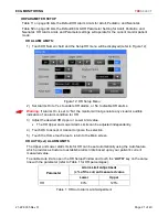
CHECKING THE ECG SIGNAL
When you have connected the patient following the steps listed above, you should be able to see
a clean ECG signal similar to the Figure 4 below on the monitor display.
If the ECG contains artifact or noise, review the steps for proper electrode site preparation and
placement (see following pages).
The Monitor should display a value for the patient's heart rate (HR) and alarm limit settings.
Alarm Limits
Name
Units
Value
Figure 4: ECG Waveform section of Main screen
The ECG and Heart Rate Monitoring settings and specifications may be found in the
SPECIFICATIONS chapter of this manual.
Procedures for changing configuration settings, such as sourcing pulse rate (PR) from SpO
2
while still displaying an ECG waveform, enabling a Pulse tone, displaying multiple ECG
waveforms, or adjusting alarm limits, may be found in the ECG SETUP chapter.
The fixed square reference wave to the left of the ECG waveform indicates the height
of a 1mV QRS associated for the current lead selection.
The size of the 1mV ref is dependent on ECG waveform Size selected
Another verification method is the ability to inject a 1 mV pulse on the ECG Waveform, refer to
CAL PULSE under the HR PARAMETER SETUP Section, starting on page 24.


