background image

H0548500.A - EN - 2015-11

5


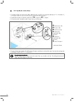
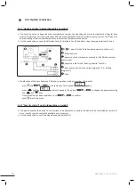
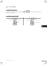
 2.2 I  Hydraulic connecti ons

•  

The device will be connected with a Ø40 or Ø50 PVC pipe, using the connectors supplied (see § “1.1 I  Descripti on”), 

to the pool's fi ltrati on circuit, aft er the fi lter and before the water treatment.

•  

Respect the directi on of hydraulic connecti on ( 

 = input and  

  = output).

•  

A by-pass must be installed to make it easier to work on the device.

water entry valve

: by-pass valve

water exit valve

water entry 

adjustment valve 

(opti onal)

water exit 

adjustment valve 

(opti onal)

: water treatment

* minimum distance

•  

To evacuate the condensati on, fi t a Ø15 pipe on the grooved elbow to be mounted under the device base (supplied 

according to model, see § “1.1 I  Descripti on”).

Tip: condensati on drainage

Cauti on,  several  litres  of  water  must  be  drained  from  your  device  each  day.  We  strongly  recommend 

connecti ng the drainage to the sewers  

Содержание Z200 M2

Страница 1: ...H0548500 A 2015 11 Instructions for installation and use English More documents on www zodiac poolcare com Z200 PI20 Power Everpac EN...

Страница 2: ...you read this installation and user manual as well as the warnings and warranty booklet delivered with the device Failure to do so may result in material damage or serious or fatal injury and will in...

Страница 3: ...h plug except PI2051 with plug except 11M C Joint x2 D Screw in connector x2 E 40 adaptation x2 F 50 reduction x2 G Condensation evacuation kit 15 H Wintering cap x2 I Wintering cover Heating priority...

Страница 4: ...3G1 5 3G1 5 3G2 5 3G2 5 Proof pressure bar 6 Service pressure bar 1 5 Head loss mCE 1 1 1 5 1 5 Minimum optimum water ow rate m h 4 6 8 8 Maximum water ow m h 10 Values provided for information purpos...

Страница 5: ...connectors Top view of the device with dimensions for attachment to the ground The device must not be installed In a location subject to high winds With the blowing towards a permanent or temporary o...

Страница 6: ...installed to make it easier to work on the device water entry valve by pass valve water exit valve water entry adjustment valve optional water exit adjustment valve optional water treatment minimum d...

Страница 7: ...device s information plate The electricity supply cable must be insulated against any cutting or hot elements that may damage or crush it The equipment must be connected to an earth socket The electri...

Страница 8: ...er power contactor tripolar or bipolar for the ltration system pump motor separate cable for the heating priority function heat pump terminal see wiring diagram 5 3 I Wiring diagrams fuse Modi cation...

Страница 9: ...ating range to heat up Cover the basin with a sheet bubble canopy canvas etc to prevent heat loss Take advantage of a period with mild outdoor temperatures on average 10 C at night your heat pump will...

Страница 10: ...ulation running Close valve B gradually so that the lter pressure is increased by 150g 0 150 bars Open valves A C and D fully then valve E by half the air which has built up in the heat pump condenser...

Страница 11: ...ater is circulating through the heat pump press ashes for 10 seconds then the setpoint temperature is displayed xed 3 4 2 Locking unlocking the keyboard Locking the keyboard Unlocking the keyboard Pre...

Страница 12: ...the heat pump 4 2 I Maintenance It is recommended that the device be general serviced at least on a yearly basis to ensure proper operation maintain performance levels and prevent some potential fail...

Страница 13: ...mp cannot manage to deice its evaporator it will stop itself this means that the outdoor temperature is too low below 7 C The device is not working If there is no display check the supply voltage and...

Страница 14: ...Insu cient water ow Increase ow using by pass check that the pool lter is not clogged Water temperature too high 32 C maximum Wait until the temperature falls Flow controller blocked Check the ow con...

Страница 15: ...relay Earth KM4 Complementary relay C1 Compressor condenser M1 Compressor C2 Ventilator condenser M2 Ventilator CD Flow controller SD1 Water temperature sensor E1 High pressure switch SD2 Air temperat...

Страница 16: ...49180 St Barth l my d Anjou cedex S A S U au capital de 1 267 140 SIREN 395 068 679 RCS PARIS Votre revendeur Your retailer Mod le appareil Appliance model Num ro de s rie Serial number Trouvez plus d...

Отзывы: