ECI1A00 Network Motion Control Card Hardware Manual Version1.0
19
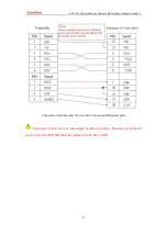
Some servo drives are not optocoupler isolation (such as, Panasonic economical
servo), now the first pin GND must be connected with drive GND.
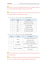
J1-J16 consists of 8 axes interface, each two terminals constitute one axis signal.
For example, J1 and J2 is the AXIS 0 interface signal.
→
(J1 J3 J5 J7 J9 J11 J13 J15) terminal definition:
PIN
Signal
Description
1
GND
Internal power ground
2
+5V
In5V power output
3
PUL-
Axis pulse output
4
PUL+
Axis pulse output
5
DIR-
Axis directional output
6
DIR+
Axis directional output
→
(J2 J4 J6 J8 J10 J12 J14 J16) terminal definition:
PIN
Signal
Description
1
OVCC
+24V output (recommended to be
only for servo IO)
2
OGND
External power ground
3
IN38-45/ALM
General input, recommended to do
drive alarm
4
OUT12-19/ENABLE
General output, recommended to do
drive enable
There is ALM input in the axis signal, which is the same as general input, wiring
refers to general input.
There is ENABLE output in the axis signal, wiring refers to general output, and
there is no over-load protection, which is recommended to do motor enable.

