

14.
Install the digital decoder board onto the upper pins of interior details part (see
previous picture for reference) and press them with soldering iron heated up to
200 °C in order to fix the circuit board completely.
CAUTION: Digital decoder circuit board is very thin - only 0.2 mm. Making it so thin
is the only way to fit all electronic components in a very limited space inside the
railbus without making irreversible modifications to the model. Please handle the
circuit board very carefully and never bend it!
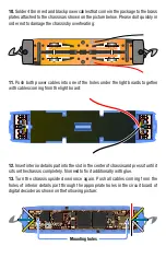
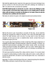
15.
Solder all cables to the pads on the digital decoder board as shown below:
16.
Now the electric part of assembly is complete. At this step, do not install the
housing yet, but place the railbus on the track, turn on the command station and
check if all light functions work correctly. You may need to move the chassis
manually on the tracks in order to establish initial electric contact that may be
unstable during very first run.
You may also adjust the brightness of interior lighting at this stage (brightness of
headlights and tail lights can be adjusted later via decoder settings). To do this, use
small slot head screwdriver and adjust the trimmer resistor on the circuit board.
Turning clockwise increases the brightness, and vice versa. Please support the
circuit board with your hands during this in order not to damage it accidentally due
to excessive pressure.
17.
Carefully install the housing of the railbus onto the chassis. It is recommended
to couple the railbus trailing car with another railbus with motor or with a different
locomotive and perform a break-in run at the full speed from 5 to 15 minutes in
both directions.
Important: To achieve best driving performance, please always keep the wheelsets
of the railbus and tracks clean from dust, fiber and grease.
Track 1
Track 2