


Installation
IMPORTANT: Soldering work required for installation of this decoder. Soldering
station with adjustable temperature control, soldering iron with thin tip (1-1.5 mm)
and good soldering skills needed for this.
1.
Prior to installing the digital decoder, make sure your railbus runs perfectly in
analog mode without flickering of the light.
2.
Carefully remove the housing of the railbus from the chassis.
3.
Unsolder all wires from the top of the circuit board that is attached to the interior
details insert.
4.
Reduce the temperature of the soldering iron down to 200 °C and heat up
pressed plastic pins which hold the circuit board. At the same time, slowly pull the
circuit board upwards, so that it will separate freely.
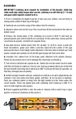
5.
Separate interior details insert from the chassis. To do this, insert a wide slot
head screwdriver, guitar pick either a similar object into the center of the gap
between the black metal weight plate attached to the blue interior details part and
plastic chassis and carefully turn it until the parts separate from each other.
6.
Unsolder four cables from to the brass parts attached to the plastic chassis.
Please do it quickly in order not to damage the chassis by overheating.
7.
Turn interior details insert upside down. Carefully hock the small circuit boards
with thin slot head screwdriver. One by one, heat up pressed plastic pins that hold
the boards with soldering iron heated up to 200 °C and pry the boards upwards, so
that they will separate completely.
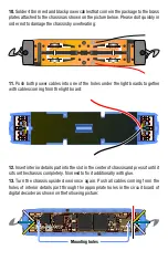
8.
Install new light boards with pre-soldered wires that come with a digital decoder
instead of old ones and press them gently until they sit on the pins completely.
Push pre-soldered cables coming from the light boards into the holes under the
circuit boards. Press two plastic pins with soldering iron heated up to 200 °C in
order to fix the light boards in place.
9.
Attach supplied light filters onto the ends of chassis with a small drop of glue
(plastic or lasercut) as shown on this picture: