background image

CANFDNET-400U


High-performance Four-channel CANFD Bus to Ethernet Converter User Manual


©2021 Guangzhou ZLG Electronics Co., Ltd.


User Manual


4.5  CANFD-bus Interfaces 

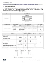
The device provides four isolated CANFD-Bus interfaces. The shell identification is "CAN0", "CAN1", "CAN2", 

and  "CAN3".  The  physical  form  of  the  interface  is  a  DB9  terminal.  Table  4.6,  Table  4.7  and  Table  4.8  list  the 

interface diagram, signal definition, and interface specifications. 

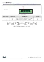
Table 4.6 Pin definitions 

Type 

Schematic Diagram 

Pin definitions 


Table 4.7 Signal definition 

Function Interface 

Signal Definition 

Signal Description 

Pin Number 

CANFD0~CANFD3 

CANFD_L 

CANFD data transceiver differential inverted signal 

CANFD_GND 

CANFD isolation ground 

3, 6 

CANFD_H 

CANFD data transceiver differential positive phase signal 

CANFD_FG 

Shielding ground 

NC 

Not connected 

1, 4, 8, 9 

Table 4.8 CANFD-Bus interface specifications 

Parameter 

Minimum 

Typical Value 

Maximum 

Unit 

Communication baud rate 


5k 


1M 

bps 

Number of nodes 


110 

pcs 

Dominant level (logic 0) 

CANFDH 

2.75 

3.5 

4.5 

CANFDL 

0.5 

1.5 

Recessive level (logic 1) 

CANFDH 

2.5 

CANFDL 

2.5 

Differential level 

Dominant (logic 0) 

1.2 

3.1 

Recessive (logic 1) 

-0.5 

0.05 

Maximum withstand voltage of the bus pin   


-18 


18 

Instantaneous voltage of the bus 


-100 


+100 

Isolation voltage (DC) 


3500 


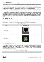
Figure 4.2 Typical high-speed CANFD network connection 

Содержание CANFDNET-400U

Страница 1: ...eywords CANFD BUS message forwarding Ethernet Abstract Product User Guide 2021 Guangzhou ZLG Electronics Co Ltd CANFDNET 400U User Manual CANFD Bus to Ethernet Module Products UM01010101 1 0 00 Data 2019 03 11 User Manual ...

Страница 2: ...CANFDNET 400U High performance Four channel CANFD Bus to Ethernet Converter User Manual 2021 Guangzhou ZLG Electronics Co Ltd 2 User Manual Revision History Version Date Reason V1 00 May 13 2020 Created ...

Страница 3: ...n Level 3 3 Mechanical Dimensions 4 4 Hardware Interfaces 6 4 1 Panel layout 6 4 2 Indicators 6 4 3 Button 7 4 4 Power Interface 7 4 5 CANFD bus Interfaces 8 4 6 Ethernet Interface 9 4 7 Vehicle Ethernet Interface 9 5 Quick Guide 11 5 1 Device Connection 11 5 2 Software Installation 11 5 3 Running the Device Configuration Tool 11 5 4 Device Search 12 5 5 Basic Device Configurations 13 5 5 1 Config...

Страница 4: ...tion software 1 2 Product Features 1 2 1 Powerful Hardware High speed dual core A9 FPGA processor 100M 1000M self applicable Ethernet interface 2 kV electromagnetic isolation Car dual wire Ethernet meeting 100Base T1 specification Four CAN FD ports 2 5 kVDC withstand voltage isolation Rated power supply voltage range 9V 48V DC Operating temperature 40 C to 85 C Humidity 5 95 RH no condensation Rug...

Страница 5: ...elopment interface function library is provided Windows and Linux platforms supported You can configure the working parameters by using the configuration tool and provide the secondary development interface function library Windows Linux platforms supported Support TCP UDP data conversion between vehicle Ethernet and Ethernet Support local system firmware upgrade 1 2 3 Typical Applications High sp...

Страница 6: ...vel Test Voltage kV Test Result Remarks Power supply Level 4 6 Class A Contact discharge CANFD bus Level 4 6 Class A Contact discharge Ethernet Level 4 6 Class A Contact discharge Buttons Indicators Level 4 15 Class A Air discharge Table 2 4 Protection level electrical fast transient pulse group immunity test IEC61000 4 4 Interface Test Level Test Voltage kV Test Result Remarks Power supply Level ...

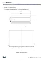
Страница 7: ...s to Ethernet Converter User Manual 2021 Guangzhou ZLG Electronics Co Ltd 4 User Manual 3 Mechanical Dimensions The mechanical dimensions are shown in the following figure unit mm Figure 3 1 Host dimensions diagram 1 Figure 3 2 Host dimensions diagram 2 ...

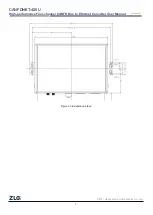
Страница 8: ...CANFDNET 400U High performance Four channel CANFD Bus to Ethernet Converter User Manual 2021 Guangzhou ZLG Electronics Co Ltd 5 User Manual Figure 3 3 Installation method ...

Страница 9: ...tus Status Description Flash description PWR Power indicator Light off The device is not powered on Red The device is powered on properly SYS System indicator Green flashing light System running 100 ms cycle after ON twice wait for 500 ms Always red Device reset and restart LAN0 Ethernet indicator Light off Ethernet no connected Green normally on Ethernet connected Green flashing The application h...

Страница 10: ...tton function Identification Function RST DEF Resets the device press Restore factory settings 5s 4 4 Power Interface The rated voltage of the power input of the equipment is DC 9 48 V and the shell is marked as DC 9 48V The physical form of the interface is a 5 08 terminal Table 4 3 Table 4 4 and Table 4 5 list the interface diagram signal definition and interface specifications Table 4 Power int...

Страница 11: ...al Description Pin Number CANFD0 CANFD3 CANFD_L CANFD data transceiver differential inverted signal 2 CANFD_GND CANFD isolation ground 3 6 CANFD_H CANFD data transceiver differential positive phase signal 7 CANFD_FG Shielding ground 5 NC Not connected 1 4 8 9 Table 4 8 CANFD Bus interface specifications Parameter Minimum Typical Value Maximum Unit Communication baud rate 5k 1M bps Number of nodes ...

Страница 12: ...ded twisted pair or standard bus communication cable In long distance communication the terminal resistance value needs to be selected according to the communication distance cable impedance and number of nodes 4 6 Ethernet Interface The device provides one Ethernet interface The physical form of the interface is RJ45 or M12 terminal parallel connection PHY is one channel which realizes the commun...

Страница 13: ...nics Co Ltd 10 User Manual 5 08 terminal Table 4 11 Signal definition Function Interface Signal Definition Signal Description Pin Number LAN1 P LAN1 data transceiver differential positive phase signal 1 N LAN1 data transceiver differential inverted signal 2 Figure 4 3 Typical network connection of vehicle Ethernet ...

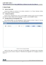
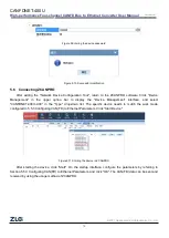
Страница 14: ...stallation package Follow the installation instructions to install the software After the installation is complete run the ZCANPRO software 5 3 Running the Device Configuration Tool After starting ZACNPRO the Device Management interface appears as shown in Figure 5 1 Click the Close button x in the upper right corner to close Device Management Figure 5 1 Device management interface Click the Tools...

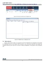
Страница 15: ...l Figure 5 3 Network device configuration tool 5 4 Device Search Click the Search Device option in the upper left corner of the Network Device Configuration tool to search for CANFDNET devices in the network After the search is over the devices connected to the network are displayed in the device list Click a device to view or modify its configurations on the right side of the configuration tool ...

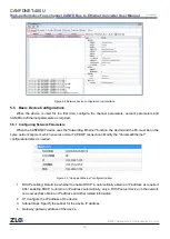
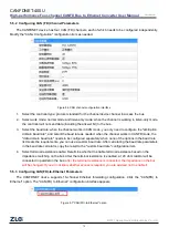
Страница 16: ...rwarding Ethernet function the device and the PC must be on the same network segment which ensures normal TCP UDP connections Modify the Universal Ethernet configuration items as needed Figure 5 5 Universal Ethernet configuration item 1 DHCP enabling Determine whether to enable DHCP to automatically obtain an IP address as required After enabling DHCP to obtain an IP address automatically only a D...

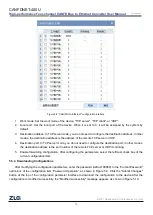
Страница 17: ...baud rate as needed when the channel works in CANFD mode the data domain baud rate needs to be configured separately when none of the options in the baud rate list meets the requirements you can use a custom baud rate After calculating the baud rate parameters in the baud rate calculator copy the result to the custom baud rate configuration item 4 Select terminal resistance enable Determine whethe...

Страница 18: ...ation port In TCP server mode you do not need to configure the destination port in other modes the destination address is the port number of the remote TCP server or UDP monitoring 5 Enable forwarding configuration After configuring the parameters select the leftmost check box of the current configuration item 5 5 4 Downloading Configurations After modifying the configuration parameters enter the ...

Страница 19: ...in the upper option bar to display the Device Management interface and select CANFDNET 400U XXX in the Type drop down list The specific device needs to match the work mode configured in 5 5 3 Configuring CAN FD to Ethernet Parameters Click Start Device Figure 5 11 Starting the device in ZCANPRO After starting the device click Start On the startup interface configure the parameters by referring to ...

Страница 20: ...CANFDNET 400U High performance Four channel CANFD Bus to Ethernet Converter User Manual 2021 Guangzhou ZLG Electronics Co Ltd 17 User Manual Figure 5 12 Starting the device ...

Страница 21: ...cs will try to present detailed and accurate product information to users in this manual However due to the effectiveness of this manual within a particular period of time ZLG Electronics does not guarantee the applicability of this document at any time ZLG Electronics shall reserve the right to update this manual without prior notice To get the latest version please visit the official website of ...

Страница 22: ...net Converter User Manual 2021 Guangzhou ZLG Electronics Co Ltd 19 User Manual Dreams come true with professionalism and dedication Guangzhou ZLG Electronics Co Ltd For more details please visit www zlg cn Welcome to call the national service hotline 400 888 4005 ...

Отзывы: