background image

iFace Series Installation Guide   


4

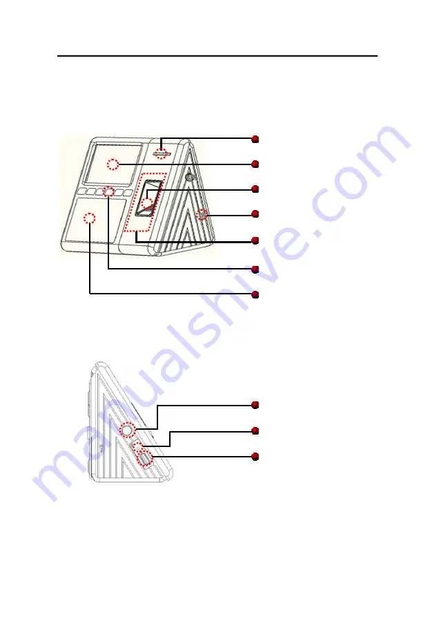
1.3 View of operation panel 

Front view 


Side view 


 LED 

light


TFT

 touch screen


 Fingerprint 

Sensor


 Baseline


 Integrated  RF  Card 

Module Read Section 

 Touch 

Keypad


 Camera


 Power 

key


Reset

 key


USB 

Содержание iFace Series

Страница 1: ...es Installation Guide Version 1 2 1 Date Oct 2010 About this Guide This guide provides actual installation instructions only For information regarding user instructions please refer to iFace Series Us...

Страница 2: ...stallation 8 3 1 Installation Steps 8 3 2 Conect with other devices 9 3 2 1 Door sensor connection 11 3 2 2 Exit button connection 11 3 2 3 Time Ring connection 12 3 2 4 Door lock connection 13 3 2 5...

Страница 3: ...is very dangerous if the power is on The short circuit of power cable may cause the core parts damage 2 All exposed part of connection wire end can not be exceeded 5mm to prevent the bared wire accide...

Страница 4: ...al personnel If the power had not met above requests it possibly causes to be unable normally to drive the electricity lock even damage the device 8 Before device to be connected please read and alway...

Страница 5: ...this equipment 1 2 Installation Environment Recommended location NOT Recommended locations Install the iFace indoors at least 10 feet 3m away from windows and 6 5 feet 2m away from light fixtures Pre...

Страница 6: ...es Installation Guide 4 1 3 View of operation panel Front view Side view LED light TFT touch screen Fingerprint Sensor Baseline Integrated RF Card Module Read Section Touch Keypad Camera Power key Res...

Страница 7: ...iFace Series Installation Guide 5 Back view Battery slot Power TCP IP USB connection terminal Loudspeaker...

Страница 8: ...iFace Series Installation Guide 6 2 The illustration of system construction 2 1 The illustration of system construction...

Страница 9: ...tion 1 Fingerprint machine directly connects with PC through RS232 or TCP IP 2 Fingerprint machine connects with PC through RS485 network 3 Fingerprint machine connects with PC through TCP IP network...

Страница 10: ...paper template We recommend affixing the template about four 4 feet 1 2m above the ground assuming the average height of your users is 5 6 feet tall 1 5m 1 85m 2 Now affix the mounting plate on the wa...

Страница 11: ...ible to damage the device badly Please follow instruction to connect peripheral equipment Door sensor connection Sensor GND Exit button connection Button GND Alarm connection NC2 COM2 NO2 Door lock co...

Страница 12: ...ase button 6 Button Connect to Release button Tie up together 7 NO1 8 COM1 9 NC1 Connect to Lock Tie up together 10 485 11 485 RS485 communication Tie up together 12 GND Connect to RS232 and Wiegand G...

Страница 13: ...2 2 Exit button connection The exit button is installed for in door operation When the switch of the button is close the door will open The distance is approximately 1400mm from ground to exit button...

Страница 14: ...ll to the fingerprint machine when arrive the appoint time the fingerprint machine will send signal to trigger relay The terminal supports both Normal Open bells and Normal Close bells at the same tim...

Страница 15: ...ce EMF to affect the access control system you need to parallel one FR107 diode do not reverse the polarity Please use the equipped diode in the package Select electric lock it is better to use strike...

Страница 16: ...be used for NC lock the NC terminal will be used This access control machine is powered by DC12V and work current 400mA If the lock work electric power is DC12V and the work current is less than 1000m...

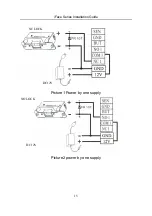
Страница 17: ...iFace Series Installation Guide 15 Picture1 Power by one supply Picture2 power by one supply NO LOCK NC LOCK DC12V DC12V...

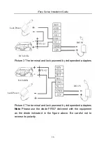
Страница 18: ...independent adapters Picture 4 The terminal and lock powered by independent adapters Note Please use the diode FR107 delivered with the equipment as the diode indicated in the figure above Be careful...

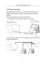
Страница 19: ...mmunication method to exchange data and remotely manage The terminal provide two ways connect Ethernet 1 The terminal connect with PC through cross cable 2 The terminal connect with PC through network...

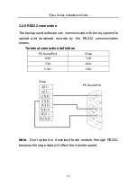
Страница 20: ...municate with the equipment to upload and download records by the RS232 communication means Terminal connection definition PC Serial Port iFace RXD TXD TXD RXD GND GND Note Don t upload or download fa...

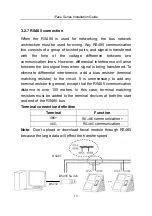
Страница 21: ...is being transferred To eliminate differential interference add a bias resistor terminal matching resistor to the circuit It is unnecessary to add any terminal resistor in general except that the RS48...

Страница 22: ...nsmission distance or a place with strong interference Note 1 The distance between device and access controller or card reader shouldn t be over 90 meters If a longer distance is needed or there is in...

Страница 23: ...by current 50mA has provided two ways to connect power please select one referring to the actual 1 Terminal connection Make sure the connection as the Diagram Don t connect the poles in reverse 2 Slot...

Страница 24: ...g all the patch correctly 2 Hang the iFace on the mounting plate top side first Please see figure 3 Then secure the iFace to the mounting plate with a screw from below Please see figure 4 After instal...

Страница 25: ...ve and other devices can work normally For more information please see the User Manual and Software Instructions 1 Upon power on the indicator begins to blank in green 2 Enter Menu Auto Check 3 Enter...

Страница 26: ...hine not to work you can restart machine through reset key take a small tool which diameter is no more than 2mm find reset mark of res on the left small hole on the bottom of device see following figu...

Страница 27: ...ction is realized by back cover pressing the anti dismantle button When the device is being dismantled it will send a alarm signal through the terminal 5 3 U flash disk using there is a mini port of U...

Страница 28: ...y you need press power key to turn on the terminal In normal state When the power cut down the reserve battery will switch into discharge state to power on the terminal In power off state when the pow...

Страница 29: ...capacity is full and the environment is 20 5 Cycle age Cycle times of charge and discharge 300 times Notice There is a danger of battery exploding leak fever fire break if you don t read the notice c...

Страница 30: ...iFace Series Installation Guide 28 Do Not throw batteries into fire or hot battery Do Not use wire or other metal short the positive and negative terminal...

Отзывы: