MONTAGE / ASSEMBLY
ZIPPER MASCHINEN GmbH www.Zipper-Maschinen.at
4
ASA550-FP
(EN) Assembly
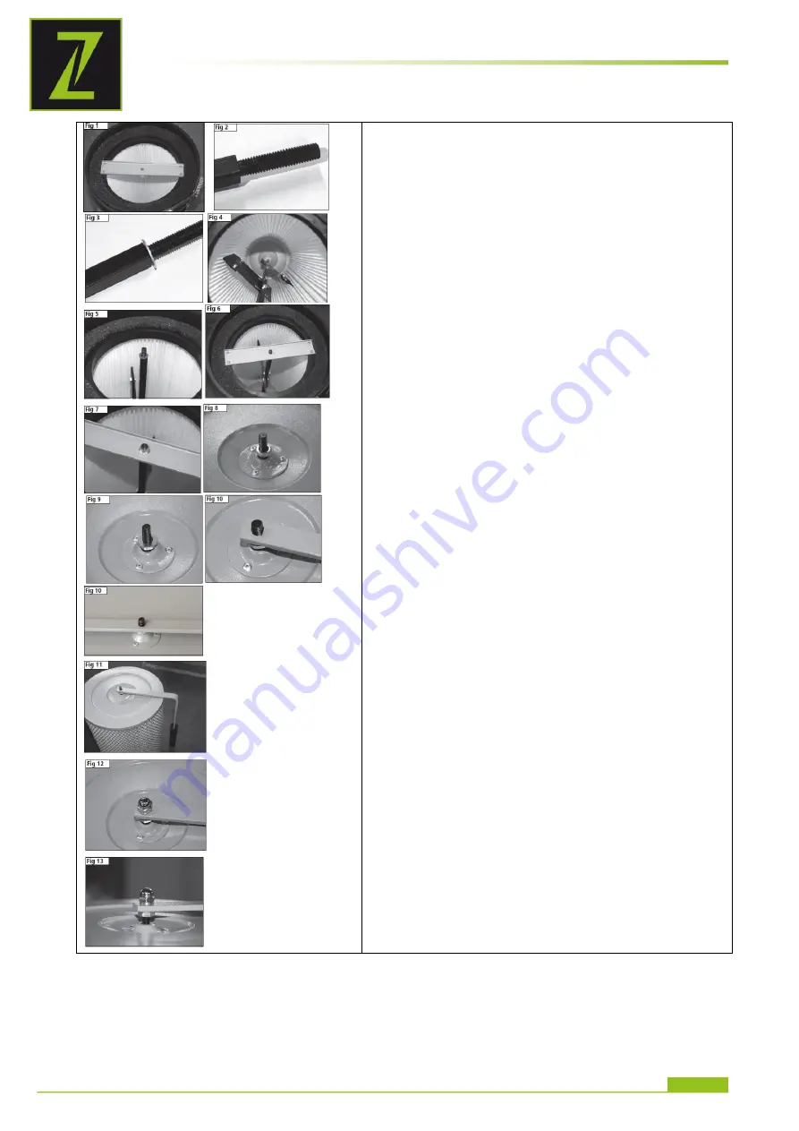
1. Remove the 4 self-tapping screws and remove the retaining
plate, Fig 1.
2. Familiarise yourself with the cleaning mechanism paddle
assembly. Note that the threaded sections at each end of the
assembly have different diameters and lengths of thread. The
longer threaded section (M10 x 45 mm) as shown in Fig 2 should
be orientated so that it protrudes through the top of the filter
cartridge. Place one of the M10 flat washers over the thread as
shown in Fig 3 and carefully feed this end of the paddle assembly
up through the filter cartridge and through the hole in the top plate
of the cartridge, Fig 4.
3. Place a M8 flat washer over the shorter thread (M8 x 16 mm) at
the other end of the paddle assembly as shown in Fig 5 and re-fit
the retaining plate using the four self-tapping screws, Fig 6.
4. Place another M8 flat washer over the thread, along with the M8
self-locking nut and tighten the nut. Note that the self-locking nut
should not be fully tightened and should allow the paddle
assembly to rotate freely when operated, Fig 7.
5. Place the M10 half nut over the M10 x 45mm threaded section
of the paddle assembly and wind it along the thread until it is just
clear of the top of the filter housing as shown in Fig 8. (do not
overtighten at this stage as the nut will be adjusted further in the
following steps).
6. Add the M10 washer, Fig 9, and the cleaning mechanism
operating handle, Fig 10. Note that the flat section of the hole in
the operating handle should be positioned so that it slides over the
corresponding flat section of the thread. The handle should now
be positioned as shown in Fig 11.
7. Add the M10 spring washer and M10 domed nut as shown in
Fig 12.
8. Tighten the domed nut in order to secure the operating handle.
At this stage the half nut can be adjusted to the correct position so
that the operating handle does not foul the top plate of the filter
cartridge. Ensure that both the domed nut and half nut are fully
tightened, Fig 13.
9. The filter cartridge can now be fitted to the suitable dust
collection machine using the securing strap provided.


