background image

30

Installation instructions 

802742UK  V4.00 Sept 2018 - Zip HydroTap Industrial

Technical support


Tel: 0345 6 005 005  Email: [email protected]  www.zipwater.co.uk

• 

Turn the power and water on and check for any leaks.

• 

If fitted, ensure the booster is turned off. (The booster is commissioned later, see page 31).

• 

Familiarise yourself with the operation of the tap, in preparation for use, see the user guide.

• 

Follow the commissioning instructions below (and read the user guide). 

• 

After commissioning, the system may be customised by selecting further options in section G - settings 

of the user guide.

Section 6

Commissioning

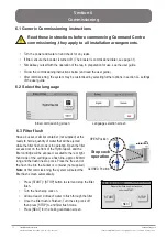
Initial commissioning screen

Language selection screen

6.1 Generic Commissioning instructions 


Read these instructions before commencing Command Centre 

commissioning, they apply to all installation arrangements.

!

6.2 Select the language

Have a bucket or similar container (not supplied) at the 

ready to hold a quantity of water that will be ejected 

while the filter flush mode is in operation. Open the filter 

access door on the front of the HydroTap


G4 and the 

filter cartridge will be exposed. Located to the rear right 

hand side of the cartridge is a flush line, approx 600mm 

long and the flush line stop cock. Place the free end of 

the flush line into the bucket or container (not supplied). 

Note


At first commissioning, the system will select the 

filter flush screen automatically.

•  Press [START] / [STOP] button to start and stop the filter  

flush. 

•  Turn the flush stop cock on.
•  Allow at least 10 litres of water to flush through the filter.
•  Once the filter flush is finished, Turn the stop cock off            

then press [STOP] to end filter flush mode. 

•  Press [NEXT] for the boiling calibration screen.

Prepare filter flush as per instructions 

and press START

Boiling Chilled

Zip

START

STOP

NEXT

03:01 PM, TUE 12, Feb 2013

OPEN Position

CLOSED Position

ON

OFF

Stop cock

operation

6.3 Filter flush

Содержание HydroTap G4 IS Industrial Series

Страница 1: ...ustrial Technicalsupport Tel 03456005005 Email service zipindustries co uk www zipwater co uk Installation instructions Zip HydroTap TheWorldsmostadvancedDrinkingWaterAppliance Model IS IT Industrial...

Страница 2: ...rvice zipindustries co uk www zipwater co uk Tap options The G4 industrial series offers a range of taps to suit the customer s needs Command Centre These standalone taps are directly compatible with...

Страница 3: ...3 15 Step 3 Install the booster if required Section 3 Booster installation 3 1 Booster specifications and descriptions 16 Pull out templates for side touch taps 17 20 3 2 3 4 Booster installation proc...

Страница 4: ...t power is available Check the under counter cupboard floor supporting the Command Centre is adequate for its total weight when full of water Before commissioning Check the system has been installed c...

Страница 5: ...nt to boil the water The boiling and chilled models will dispense boiling water factory set to 98 C chilled water factory set to 5 9 C These units are NOT designed to be used as sanitary fixtures The...

Страница 6: ...or boiling water droplets may discharge through a vent outlet on the tap If the tap is not installed using the font ensure the tap body is located so the tap outlet safely dispenses into the sink bowl...

Страница 7: ...y void warranty coverage As the installer it is your responsibility to supply if necessary and install all valves as required by local regulations and relevant standards The HydroTap G4 is rated for 2...

Страница 8: ...cold water supply with a minimum working pressure of 172kPa and a maximum working pressure of 700kPa connected via an isolation valve For the mains pressure All IN ONE both a hot and cold water supply...

Страница 9: ...ng chilled and filtered without booster 160 175 no 1x13A 2 20 N A 450 x 470 x 335 28 Boiling chilled and filtered with booster 240 175 yes 2x13A 2 20 2 20 450 x 470 x 335 28 Boiling chilled and filter...

Страница 10: ...r easy accessible 220 240V AC 13A sockets will be required One socket is for the Command Centre and the other for the booster Both the Command Centre and booster must be installed in accordance with I...

Страница 11: ...diameter sheet metal punch or hole saw to suit surface being cut Hole positioning Position the tap such that it dispenses into the sink bowl with ample clearance for a cup or tea pot Alternatively th...

Страница 12: ...ree tubes and USB cable through each of their respective holes Slide the clamp block up and secure with the M6 long series nut on the threaded rod Fit the 3 x M6 cap screws and spring washers through...

Страница 13: ...on with section 5 Command Centre installation page 26 When installing air flow vents the following tools will be required Jigsaw and drill or equivalent equipment Keyhole or wall board saw 2 1 Generic...

Страница 14: ...on either the kick board or the cupboard ends Inlet grille should be fitted in baseboard A Cupboard back must be fully closed to prevent recirculation into cupboard from kick space 2 2 BC Commercial C...

Страница 15: ...ck space duct fitted to the Command Centre B Fan kit fitted to cupboard door position B1 or side position B2 and without kick space duct fitted to the Command Centre For dual exhaust fan cut out dimen...

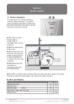
Страница 16: ...rate 1 2 L min Section 3 Booster system 3 1 Product description The booster system is a compact electronically controlled auxiliary water heater It is intended to provide pre heating of water before...

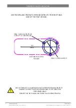
Страница 17: ...tructions 802742UK V4 00Sept2018 ZipHydroTapIndustrial Technicalsupport Tel 03456005005 Email service zipindustries co uk www zipwater co uk THIS TEMPLATE IS NOT REQUIRED FOR INDUSTRIAL TOP TOUCH TAPS...

Страница 18: ...MOUNTING TO THE RIGHT HAND SIDE OF THE FONT OR SINK BUTTONS FACE USER THIS SIDE DRILL 3 X 6 5mm HOLES ON A 43 0 P C D EQUISPACED DRILL 1 X 35 0mm HOLE TAP SPOUT Template for Industrial side touch tap...

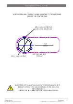
Страница 19: ...MOUNTING TO THE LEFT HAND SIDE OF THE FONT OR SINK BUTTONS FACE USER THIS SIDE DRILL 3 X 6 5mm HOLES ON A 43 0 P C D EQUISPACED DRILL 1 X 35 0mm HOLE TAP SPOUT Template for Industrial side touch tap...

Страница 20: ...20 Installationinstructions 802742UK V4 00Sept2018 ZipHydroTapIndustrial Technical support Tel 03456005005 Email service zipindustries co uk www zipwater co uk Pull out template...

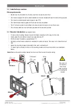
Страница 21: ...top of the booster The hot water outlet hose must be thermally insulated with the insulation provided Tilt forward Lift up Release Note Remove the wall mounting chassis from the rear of the booster fo...

Страница 22: ...d on the rating plate Connect the braided hoses from the BYPASS OUT fitting on the Command Centre to the water inlet of the booster blue cap and from the outlet of the booster red cap to the BYPASS IN...

Страница 23: ...e separately in the following document Zip scale filter head installation and operating instructions 2017 supplied with the filter head 4 1 Mounting the filter head 4 2 Cartridge installation and flus...

Страница 24: ...e of water that can flow through at one time is limited to a pre determined maximum providing the flow rate through it exceeds 2 litres per minute The Water Block also incorporates a non return valve...

Страница 25: ...is correct and that the filter screen see Fig 2 is inserted correctly with the convex surface facing towards the water supply 4 6 Installation Fig 2 Fit key to adjust flow Key Reset lever 4 7 Reset Pr...

Страница 26: ...ons in conjunction with the following Scale filter head 2017 instructions supplied with the scale filter head Section 5 Command Centre installation Install the mains water braided hoses to the Command...

Страница 27: ...2 3 4 B Rotate 90 only 1 2 3 4 5 2 External bypass valve The Boiling chilled products have an external bypass valve The external bypass valve allows the user to choose to have the boiling feed water b...

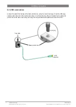
Страница 28: ...cable 4 pin plug 5 3 USB connection Connect the cable from the tap to the black junction box using the round 4 pin plug Orient the USB plug carefully and connect it to the Command Centre do not force...

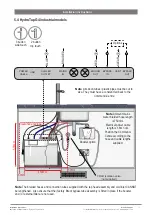
Страница 29: ...or external filter are not used Note Ambient mains water braided hose length is 750mm Electrical power cable length is 1 8m nom Position the Command Centreaccording to the hose and cable lengths supp...

Страница 30: ...nguage Have a bucket or similar container not supplied at the ready to hold a quantity of water that will be ejected while the filter flush mode is in operation Open the filter access door on the fron...

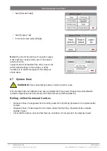
Страница 31: ...to the booster water must be run through for a min of 30 seconds to purge Run the boiling tap for 30 seconds and the allow the tank to refill Dispense boiling water for 30 seconds and check the boost...

Страница 32: ...oiling water from the boiling outlet of the HydroTap Equivalent of a complete tankful of water Dispense 6 litres of chilled water from the chilled outlet of the HydroTap Equivalent of two complete tan...

Страница 33: ...ult Call Zip service Condenser Sensor Closed Internal fault Check ventilation Call Zip service Condenser Sensor Open Internal fault Check ventilation Call Zip service Heater Driver Fault No hot water...

Страница 34: ...ed bin logo indicates that this product needs to be disposed of separately to any other household waste Within each of the European Union member countries provisions have been made for collection and...

Страница 35: ...esulting from non operation of the appliance the use of non authorised parts or consequential damage to any other goods furnishings or property No warranty applies to the life of any filtration cartri...

Страница 36: ...2UK V4 00Sept2018 ZipHydroTapIndustrial Technical support Tel 03456005005 Email service zipindustries co uk www zipwater co uk ZipWaterUK 14BertieWardWay Dereham Norfolk NR191TE 03456005005sales zipin...

Отзывы: