background image

804050US v1.27 06.21 CS175 Install Instruction 

Page 17 of 28

Commissioning

NOTE: 

For any subsequent filter changes or any operational procedures, please refer to the HydroTap user 

guide, located inside the filter housing access door.


5.3

 - 

Conditioning Procedure

Zip HydroTap Command Centers are sanitized during manufacturing and require final flushing before normal 

use. 
1.  Turn off CO

2

 gas at the regulator.

2.  Dispense 10 liters (2.6 gallons) of chilled water from the chilled outlet of the HydroTap (equivalent to 4 

complete tanks full of water.

3.  If water bubbles or foams, repeat step 2 above.

4. 

Let filled tank stand for one hour at operating temperature.

5.  After one hour, repeat step 2.

6.  Dispense 2 liters (½ gallon) of sparkling water from the sparkling outlet. Repeat the 2 liters (½ gallon) 

dispense until the water is clear.

7.  Turn on the CO

2

 gas at the regulator. The HydroTap is ready for use.

1. After product commissioning and CO

2

 purge, you are now 

ready to adjust the carbonation flow rate. 
2. To adjust the flow rate, rotate the adjustment screw anti-clock

-

wise to increase the flow and clockwise to decrease the flow.
3. To measure the flow rate you have set, use a measuring cup or 

jug and run the sparkling water for 15 seconds (the HydroTap has 

a default 15 seconds dispense time, which will help in your flow 

rate set up). Multiply the amount of water dispensed in that 15 

seconds by 4 to get your flow rate in gallons per minute. 1.6 liters 

(0.4 gallons) per minute is the optimum flow rate.

Important 

– If you adjust the flow rate too high, you will empty the 

carbonation tank of water leaving only CO

2

 to be dispensed from 

the faucet. This will result in inconsistent flow (spluttering).


5.4

 - 

Carbonation Valve Flow Adjustment

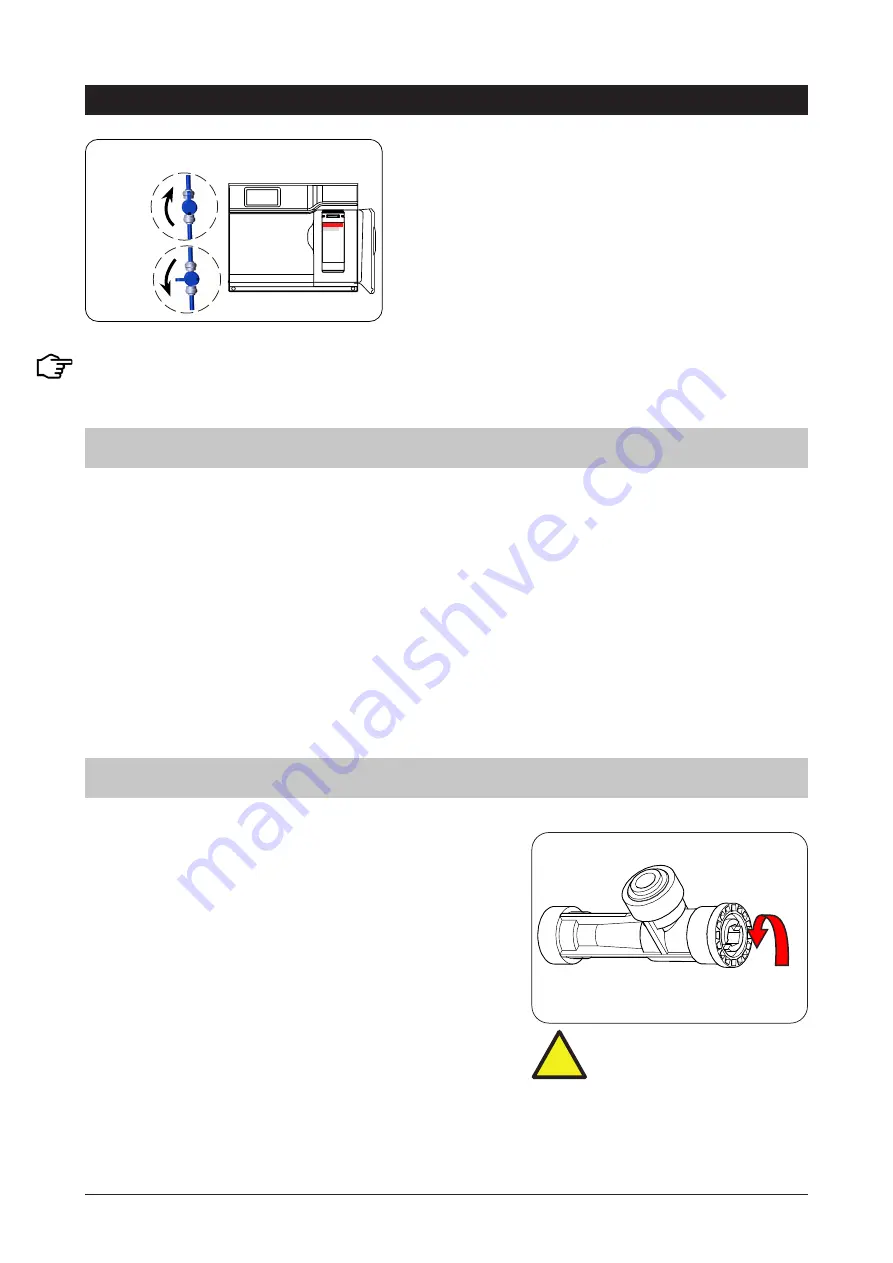
OPEN 

CLOSED 

Stop cock operation

1.  Turn the flush line stop cock ON  (See diagram).
2.  Press [Start] and allow at least 10 liters (2.6 gallons) of 

water to flush through the filter.

3.  The product details will be displayed in the screen.
4.  Once the filter flush is finished, Turn the stop cock OFF 

then press [Stop] to end filter flush mode. 

+

!

Warning 

- Take care NOT to 

use excessive force during 

adjustment of the valve. 

Содержание HydroTap CS Commercial

Страница 1: ...804050US v1 27 06 21 CS175 Install Instruction Page 1 of 28 Installation and Operating Instructions Zip HydroTap CS Commercial Scan QR Code to download the latest version of this document English French ...

Страница 2: ... customer s needs For ease of installation it is recommended to fit the faucet before installing the Command Center The installation procedure for each of the faucets is detailed in the faucet installation instruction book supplied with the faucet For all operational features of the HydroTap please refer to the User Guide Classic Arc Cube Wave Faucet options ...

Страница 3: ... Models 10 2 3 Alternative Ventilation 11 STEP 3 Fit the CO2 Gas cylinder Section 3 CO2 Cylinder and Regulator 3 1 Connect secure and test the CO2 gas cylinder 12 3 2 Connect the regulator 12 3 3 Connect the gas hose to the regulator 12 CO2 Regulator and Leak Test 13 STEP 4 Install the Command Center Section 4 Command Center installation 4 1 Hose and Tube fittings 14 4 2 J G Fittings 14 4 3 Model ...

Страница 4: ...nter cabinet supporting the appliance is adequate for the total weight of the appliance when full of water Before Commissioning 1 Check the Command Center has been installed correctly 2 Flush the supply line before connecting to the Command Center 3 Check all plumbing fittings have been tightened 4 Ensure the outlet and vent pipes are positioned to drain correctly 5 Ensure there is adequate ventil...

Страница 5: ...nce and knowledge unless they have been given supervision or instruction concerning use of the appliance by a person responsible for their safety Children should be supervised to ensure that they do not play with the appliance For products sold in Europe this appliance can be used by children aged from 8 years and above and persons with reduced physical sensory or mental capabilities or lack of ex...

Страница 6: ...zard 11 If this device is not maintained and operated as specified in this document there is a risk of exposure to contaminants CO2 Cylinder Warnings Pressurised container Protect from sunlight Contains gas under pressure may explode if heated Do not expose to temperatures exceeding 50 C 122 F Do not pierce or burn even after use Do not expose to naked flame or any incandescent material Keep out o...

Страница 7: ... kit 1x Air Duct 1x Mounting plate Vent Kit 1x Inlet vent 1x Outlet vent 9 x Screws 1x Installation Instructions this book and 1x User Guide 1x CO2 gas cylinder regulator assembly Accessories Description Font Drip Tray Kit for Arc Cube models 93580US Chrome Font Drip Tray Kit for Classic Models 93303US Chrome Replacement Filter 1 5Z LS Culligan P N 01034277 Accessibility Lever Kit for Classic Fauc...

Страница 8: ...NSF ANSI Standard 372 for low lead requirement and against NSF ANSI Standard 42 and NSF ANSI Standard 53 This will deliver the required bacteriostatic effect and the reduction of aesthetic chlorine taste odor nominal particulate Class I 0 5 µm to 1 µm cyst and lead as verified and substantiated by test data See Performance Data Sheets for specific performance claims Certified performance claims ar...

Страница 9: ... The system shall only be supplied with cold water Potable water should have a minimum TDS Total Dissolved Solids of 50 ppm In areas where the TDS exceeds 150 ppm and where mineral scale could be a problem consideration should be given to the maintenance required Adding a water softener or reverse osmosis system should be considered Ensure sufficient space for ventilation including minimum clearan...

Страница 10: ...oard saw 2 1 Ventilation for All Models Proper air circulation must be provided for all models The system will operate correctly only if the recommended air gaps are achieved during installation IMPORTANT Allow a minimum clearance envelope of 50mm 2 either side and 200mm 8 above the Command Center The vent duct and louver panels must be installed for all under floor and or door vent systems as ins...

Страница 11: ...ocal service centre for availability A B C MIN 4 Cut out details Vent tray part no 93541US optional accessory Dual exhaust fan kit part no 93156US optional accessory Vent tray installation 11 2 1 5 12 11 16 1213 16 1 11 B Cabinet floor cut out 1 Drill two pilot holes 12mm dia 2 Finish cut out using a Jigsaw C Cabinet floor cut out 1 Drill 4 pilot holes 12mm dia in corners 2 Finish cut out using a ...

Страница 12: ...easy fit over the spigot soak it in hot water before re applying Do not force the seal to fit Turn the regulator OFF by rotating the regulator knob all the way out in an anti clockwise direction NOTE Two plastic seals are supplied with a new regulator Only one is required the other is supplied as a spare part 3 3 Connect the gas hose Connect the braided gas hose to the top of the Command Center vi...

Страница 13: ... Test Stage1 1 Turn the gas OFF 2 Using soapy water applied with a sponge or with a brush cover all of the gas joints with a liberal amount of suds Stage 2 1 Turn ON the gas 2 Adjust the pressure to between 2 7 3 0 bar 39 43 psi 3 Inspect the joint for leaks 4 If any bubbles appear the joint will need to be resealed Green zone This gauge shows the pressure in the bottle and indicates when the bott...

Страница 14: ...that the tube is not distorted 1 Use a sharp knife to ensure the tube has a clean straight edge Do not cut at an angle 2 Remove any swarf or unwanted material 3 Push the tube into the John Guest fitting making sure all connections to the John Guest fittings are pushed in past the O ring to full depth at least 15mm 4 Check for a good joint by pulling back on the tube If the tube comes out of the fi...

Страница 15: ... performance and therefore CANNOT be lengthened Take time to consider hose lengths when determining the mounting positions for the options Note Mains hose length is 750mm 30 Plug and Cord length is 1800mm 70 Position the Command Center close to the outlet faucet within reach of the hose and cord lengths supplied Note Note The hoses need to have a constant downward gradient to the HydroTap to allow...

Страница 16: ...d of the flush line into the bucket or container Note You will need to Press the Start Stop buttons to start and stop the filter flush 5 2 Filter Flush Section 5 Commissioning 5 1 CO2 Purge 1 Press the START button to commence the purging process 2 Purge for 10 seconds and ensure all water has stopped flowing through the faucet You will hear the CO2 gas escaping from the faucet 3 Press the Stop bu...

Страница 17: ...t the carbonation flow rate 2 To adjust the flow rate rotate the adjustment screw anti clock wise to increase the flow and clockwise to decrease the flow 3 To measure the flow rate you have set use a measuring cup or jug and run the sparkling water for 15 seconds the HydroTap has a default 15 seconds dispense time which will help in your flow rate set up Multiply the amount of water dispensed in t...

Страница 18: ...ackflow of gas and or water out of the internal carbonator In addition to the HydroTap s integral Backflow prevention Some authorities require additional Backflow Prevention to be installed to comply with the Local State or Federal plumbing code requirements Both the Universal Plumbing Code UPC and National Standard Plumbing Code NSPC require the use of an American Society of Sanitary Engineers AS...

Страница 19: ... Open Internal fault Call Zip Service Cold sensor Closed Internal fault Call Zip Service Flood sensor Open Internal fault Call Zip Service Condenser sensor Closed Internal fault Check Ventilation Call Zip Service Condenser sensor Open Internal fault Check ventilation Call Zip service Compressor driver fault No chilled water Call Zip Service Condenser overtemp Blocked air filter Remove blockage Cle...

Страница 20: ...ispose of this product correctly This product should not be treated as domestic waste but should be taken to a dedicated recycling center for electrical and electronic equipment Immediately prior to scrapping cut off the power cable Please contact your local city council for collection center details End of Life Disposal ...

Страница 21: ...n NSF ANSI 42 and NSF ANSI 53 Substance Average Influent Challenge Concentration Max Permissible Product Requirements Reduction Requirement Average Reduction NSF ANSI 42 Aesthetic Effects Bacteriostatic Effects Unit passes NSF ANSI 42 for Bacteriostatic effects Chlorine Taste and Odor 2 0 mg L 10 50 97 4 Nominal Particulate Reduction Class I 0 5 µm to 1 µm 10 000 mL 85 99 3 NSF ANSI 53 Health Effe...

Страница 22: ...NSF ANSI 42 and NSF ANSI 53 Substance Average Influent Challenge Concentration Max Permissible Product Requirements Reduction Requirement Average Reduction NSF ANSI 42 Aesthetic Effects Bacteriostatic Effects Unit passes NSF ANSI 42 for Bacteriostatic effects Chlorine Taste and Odor 2 0 mg L 10 50 97 4 Nominal Particulate Reduction Class I 0 5 µm to 1 µm 10 000 mL 85 99 3 NSF ANSI 53 Health Effect...

Страница 23: ...NSF ANSI 42 and NSF ANSI 53 Substance Average Influent Challenge Concentration Max Permissible Product Requirements Reduction Requirement Average Reduction NSF ANSI 42 Aesthetic Effects Bacteriostatic Effects Unit passes NSF ANSI 42 for Bacteriostatic effects Chlorine Taste and Odor 2 0 mg L 10 50 97 4 Nominal Particulate Reduction Class I 0 5 µm to 1 µm 10 000 mL 85 99 3 NSF ANSI 53 Health Effect...

Страница 24: ...2 and NSF ANSI 53 Substance Average Influent Challenge Concentration Max Permissible Product Requirements Reduction Requirement Average Reduction NSF ANSI 42 Aesthetic Effects Bacteriostatic Effects Unit passes NSF ANSI 42 for Bacteriostatic effects Chlorine Taste and Odor 2 0 mg L 10 50 97 4 Nominal Particulate Reduction Class I 0 5 µm to 1 µm 10 000 mL 85 99 3 NSF ANSI 53 Health Effects Cyst Min...

Страница 25: ...eplace the Zip Product Determination to repair or replace will be in Zip s sole discretion Repair or replacement services will be at no cost to the Zip Customer provided that a the Zip Product is installed and used strictly in accordance with the instructions supplied and b all service under the One 1 Year Limited Warranty is carried out only by an authorized Zip service technician or an approved ...

Страница 26: ... Servicer Provider who performed the warranty service the purchase date a detailed description of the problem and the address and phone number at which the Zip Customer can be reached Zip is committed to review each such notice promptly and thoroughly and to respond to the Zip Customer in order to settle such dispute Any decision is not binding Any controversy or claim arising out of Zip Customer ...

Страница 27: ...804050US v1 27 06 21 CS175 Install Instruction Page 27 of 28 Notes ...

Страница 28: ...ard 42 and NSF ANSI Standard 53 This will deliver the required bacteriostatic effect and the reduction of aesthetic chlorine taste odor nominal particulate Class I 0 5 µm to 1 µm cyst and lead as verified and substantiated by test data See Performance Data Sheets for specific performance claims Certified performance claims are only valid when filter cartridge 1 5Z LS Culligan Part Number 01034277 ...

Отзывы: