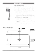
background image

17

805812 v1.04 05.20 HydroChill Install Instructions

Step 2 – Install Chiller

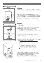
2.1 Positioning

The chiller must be placed in a hygienically suitable environment, on 
a surface capable of bearing the weight of the machine complete with 
water. Do not place close to direct or indirect heat sources (ovens, 
stoves, radiators, etc.).
Locate close to electricity and water supply points. Ensure the 
power cable and water hose do not form an obstruction. The water 
connections and condenser need to be accessible for maintenance. 
Protect from water splashes and place in a location with the 
temperature appropriate to the climate class stated on the EC 
nameplate, otherwise malfunctions may occur and warranty rights are 
forfeited.

2.2 Ventilation
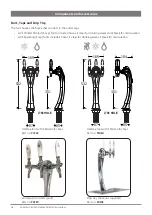
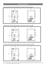
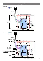
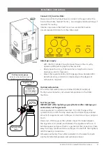
Allow a minimum clearance of 200mm around the back, top and 
sides of the chiller unit.

For installation in an enclosed single cupboard, the  vent kit and a 
double auxiliary fan kit (part no 93159) must be installed. 

•  Install the kickboard vent grille for external air intake.
•  Install the fan at the top of the cupboard to extract hot air out of 

the cupboard (requires additional electrical power outlet).

•  Cut-out in the cabinet floor.

For installation in an enclosed, double cupboard, the minimum 
ventilation requirement is:

•  Perforated or expanded metal door with at least 60% open area
•  2x cut-outs in the cabinet floor to provide air intake.

If ventilation is insufficient, additional vents and fans may be installed 
as optional extras. Contact Zip service for details.

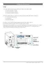
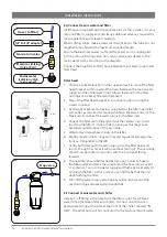
2.3 Overflow connection

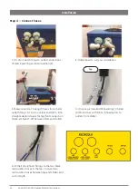
Check the overflow connector is not obstructed. Use a tube to 
connect the overflow drainage connector (A) from the tank to a 
drainage point or a large container (not supplied).
A tundish to comply with AS3500 may be required if the unit is 
installed in a cupboard, or in an area not utilising a floor waste.

Installation instructions

EC climate classes:
SN - For ambient temperatures from 10°C to 32°C
N - For ambient temperatures from 16°C to 32°C
ST - For ambient temperatures from 18°C to 38°C
T - For ambient temperatures from 18°C to 43°C

100- 200

mm

200

mm

100-200

mm

200

mm

200

mm

Содержание HydroChill Te-Mix Aqua 15

Страница 1: ...1 805812v1 0405 20HydroChillInstallInstructions Installation instructions usermanual Zip HydroChill InstantChilledandSparklingwater Models HCF90 HCF120 HCF200 HCS90 HCS120 HCS200 AFFIXPRODUCTLABELHERE...

Страница 2: ...ion instructions 16 Step 1 Install the Tap Font 16 Step 2 Install Chiller 17 Step 3 Connect Carbon Dioxide CO2 Cylinder 20 Step 4 Connect hoses 22 Step 4 Commissioning 24 Operation 25 Maintenance 26 D...

Страница 3: ...dren aged from 8 years and above and persons with reduced physical sensory or mental capabilities or lack of experience and knowledge if they have been given supervision or instruction concerning use...

Страница 4: ...ng children with reduced physical or sensory capacities or with a lack of experience and knowledge unless under supervision and with the instructions of someone responsible for their safety Make sure...

Страница 5: ...with a filter to dispense Still water at room temperature Still chilled water Sparkling chilled water The water is carried through thermally insulated tubes from the chiller to the font The insulating...

Страница 6: ...ct to the outlet taps HCF Chilled Filtered 2 tap fonts include 4 hoses 2 clear for drinking water and 2 black for recirculation HCS Sparkling 3 tap fonts include 5 hoses 3 clear for drinking water 2 b...

Страница 7: ...13 805301 CO2 Regulator 1 14 805955 3 8 x 3 8 Straight Adaptor not shown 2 Item Part No Description QTY 1 805587 Armaflex 2 m 2 805467 JG 3 8 Hose Natural White 5 m 805469 JG 3 8 Hose Blue 5 m 3 80558...

Страница 8: ...ification Te Mix Aqua 15 L HCS90 HCF90 add 25mm for roller feet 40mm for handles Te Mix Aqua 25 L HCS120 HCF120 add 25mm for roller feet 40mm for handles Te Mix Aqua 50 L HCS200 HCF200 add 25mm for ro...

Страница 9: ...21 Cold water coil AISI 304 Stainless Steel Refrigerant R134a Compressor cooling power W at ambient 32 C 400 513 905 Carbonation pump L h 200 200 300 Carbonator volume cc 1100 1100 2000 Carbonation p...

Страница 10: ...10 805812v1 0405 20HydroChillInstallInstructions Technical specification Te Mix Aqua 15 HCS90 HCF90...

Страница 11: ...NEL 9 CARBONATION PUMP order code 2311361 10 CARBONATION PUMP MOTOR 11 FAN UNIT 12 CONDENSER 13 DEHYDRATOR FILTER 14 OVERFLOW DRAINAGE 15 DRAINAGE POINT FOR EMPTYING TANK 16 ON OFF LIGHT SWITCH 17 THE...

Страница 12: ...12 805812v1 0405 20HydroChillInstallInstructions Technical specification Te Mix Aqua 25 50L HCF 120 HCF 200 HCS 120 HCS 200...

Страница 13: ...EVAPORATOR 7 INSULATING TANK 8 SIDE PANEL 9 FAN AND FAN MOTOR 10 DEHYDRATOR FILTER 11 CONDENSER 12 LEVEL CONTROL UNIT 13 CARBONATION PUMP MOTOR 14 CARBONATION PUMP 15 RECIRCULATION PUMP SOCKET 16 THER...

Страница 14: ...k will not be obstructed when the under counter chiller is installed D A 350 kPa 3 5 bar pressure limiting valve supplied must be fitted E All plumbing must comply with the relevant parts of AS NZS 35...

Страница 15: ...ip tray supplied separately no cut out required Drip tray options Zip Water Pty Ltd BKL001 HydroChill HCF HCS AU NZ v1 11 04 20 100 200 min clearance 200 min clearance 333 425 491 610 650 745 900 900...

Страница 16: ...ugh the 50 mm hole Fit the rubber base seal supplied to the base of the tap font to seal it on the benchtop Secure the font from under the bench with the washer and nut Option Recessed drip tray part...

Страница 17: ...tall the kickboard vent grille for external air intake Install the fan at the top of the cupboard to extract hot air out of the cupboard requires additional electrical power outlet Cut out in the cabi...

Страница 18: ...Unpack the filter cartridge and remove the sanitary cap Avoid touching the filter O rings or filter opening as this may cause bacterial contamination of the cartridge 5 Write today s date where shown...

Страница 19: ...l the water tank Remove the upper cover B by loosening the fixing screw Fill the tank with clean water until the level is about 2 cm 1 inch below the hole C of the overflow connector Ensure no foreign...

Страница 20: ...bly fit with sufficient clearances before securing the bracket Connect the pressure regulator The pressure regulator is supplied with interchangeable colour coded pressure relief valves The GREY colou...

Страница 21: ...arbonation Ensure the inlet water pressure is below 300kPa 3 bar 45 psi To improve carbonation set a lower temperature on the chiller machine Test for gas leaks IMPORTANT After replacing a gas cylinde...

Страница 22: ...hiller Step 4 Connect hoses Installation Tap 1 Fit John Guest fittings to outlet connections Chilled Sparkling and Recirculation 2 4 Once tap is installed fit Sparkling Chilled Ambient lines with 3 8...

Страница 23: ...t Armaflex to fit and wrap hoses to tap 7 Tightly wrap split Armaflex for condensation control 8 Wrap but expose the stop valves up to the Tap so adjustment can be made if necessary Mark the stop valv...

Страница 24: ...lation for the water to reach optimum chilled temperature If the water circuit freezes turn power OFF for at least 12 hours to defrost Adjust the thermostat anti clockwise HCS Sparkling models Adjust...

Страница 25: ...upply and the valve of the CO2 bottle Protect from heat and bad weather Keep covered to protect from dust and or splashes Sanitise the system and flush the filter before resuming operation Moving the...

Страница 26: ...etergent To prevent damage do not use abrasive materials solvents alcohol etc Do not clean with water jets Clean the dispensing nozzles with a diluted hydrogen peroxide solution or sanitisation wipes...

Страница 27: ...roughly with clean water to make sure that all traces of sanitising agent have been eliminated completely Sanitisation procedure Switch off the machine and dispense through the taps until the system i...

Страница 28: ...ime 1 Disconnect power and water 2 Remove the upper cover 3 If ice has formed allow 12 hours for the ice to melt 4 Refer to the drainage system A 5 Loosen the fixing screw B 6 Hold the upper end of th...

Страница 29: ...rt the tube in the lower slot of the plastic clip G 10 Turn the tube and insert it in the front of the upper slot H Slide the tube so you can insert the plastic clip in its seat 11 Press the clip and...

Страница 30: ...ve Do not adjust the regulator Inspect carbonator liquid check valve every 12 months The carbonator liquid check valve prevents carbonated water from flowing backwards into the potable water supply In...

Страница 31: ...npack the replacement cartridge and write today s date where shown on the label 6 Remove the sanitary cap Avoid touching the filter O rings or filter opening as this may cause bacterial contamination...

Страница 32: ...off water supply and the valve of the CO2 bottle Protect the chiller from heat dust and water splashes If the machine needs to be moved stored or shipped the system must be sanitised All water must be...

Страница 33: ...when room temperature drops below 4 4o C Contact plumbing professional if you are uncertain how to check your water pressure Do not install where water hammer conditions may occur If water hammer cond...

Страница 34: ...e closed Open the water valve Water supply hose crushed or obstructed Check and correct the path of the hose No electricity supply Check the power switch electrical cable and connections Water is froz...

Страница 35: ...corrosive spray or abrasive cleaners Clean the case with a soft cloth or brush and mild soap and water Clean the tap with a damp cloth In order to help preserve our environment we ask that you dispos...

Страница 36: ...AP 1800 947 827 Zip products described in this publication are manufactured under one or more patents and further patent applications are pending As Zip policy is one of continuous product improvement...

Отзывы: