


Page 70 MS - SOUND decoders MS440 to MS990 and MN - NON-SOUND decoders MN170 to MN340
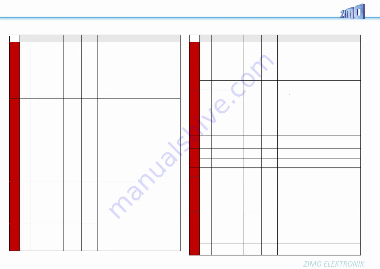
CV
Denomination
Range
Default Description
alternative to CV
#124:
Selecting a function
key for half
speed
30
and
bits 7, 6, 5
for
Setting
Half-
speed.
CV #155: Determination of the function key, with which the
half speed (= highest speed step results in half speed) can
be switched on.
If CV #155 > 0 (i.e. a key is set), a possible assignment in
CV #124 is ineffective.
If CV #155 =
= 0: CV #155 is not active, so CV #124 is valid.
= 1 - 28: Function key F1 - F28
= 29: Function key F0
= 30: MAN key
Bits 7, 6, 5: Modification of the "half" speed".
= 000: Speed according to speed step, multiplied by
0.625
= 001 ... 100: ... speed step, multiplied by 0.125 ...0.5
= 100 ... 111: ... speed step, multiplied by 0.5 ...0.875
#156
to be preferred for
new projects
alternative to CV
#124:
Selecting
a function key for
deactivating momen-
tum
0,
1 - 28,
29,
30,
129 - 156,
157,
158
0
This CV overwrites the setting of the F keys in CV #124
(bit 2&6) in case it is not satisfactory. The set range (bit
0&1) of the acceleration behavior does not change.
If CV #156 > 0 (i.e. a key is set), any assignment in
CV
#124 is ineffective.
If CV #155 =
= 0 means CV #155 is not active, so CV #124 is valid.
= 1 - 28: Function key F1 - F28
= 29: Function key F0
= 30: MAN key
Bit 7 = 1: Suppression of switching the light when revers-
ing direction.
The settings of CV #124 about the type of deactivation or
reduction still apply, thus:
CV #124, Bit 1, 0 =
= 00: no influence on acceleration times
= 10: reduces acceleration/deceleration time
to ¼ of the values according to CVs #3, #4.
= 11: deactivates acceleration/deceleration time
completely.
Typically, CV #124 = 3 is set to achieve full deactivation
(unless other bits in CV #124 are also set).
#157
Selection of a
Function key for the
MAN-function
Only for non-ZIMO
controllers that don’t
have a dedicated
MN key.
0 - 19
0
The MAN function (or MAN key on ZIMO controllers) was
originally designed for ZIMO applications only, in order to
cancel stop and speed limit commands applied by the
“signal-controlled speed influence” system (HLU).
This function was expanded in later software versions to
include “asymmetrical DCC signal stops” (Lenz ABC).
If ZIMO decoders are used with non-ZIMO systems
which do not have this key (rarely with HLU, usually with
ABC), a function key can now be assigned with CV #157
to cancel a signal-controlled speed limit or stop com-
mand.
#158
Various special bits
Bits 1, 3, 5, 6, 7
(only Diesel & Electro)
-
Bit 1 = 1: Diesel mechanical: RPM is not raised
when braking (see CV #364).
Bit 2 = 0: RailCom speed feedback (km/h)
feedback in “old” format (for
MX31ZL, RailCom ID 4)
= 1: RailCom speed feedback (km/h)
Normal feedback (RailCom ID 7)
CV
Denomination
Range
Default Description
Bit 3 = 1: (DIESEL) Sample for standstill is
faded out when driving-
off “early”.
Bit 4 = 1: Steam chuff frequency increases slower
at high speed (non-proportional)
Bit 5 = 1: (DIESEL) Braking (even by one speed
step) causes the motor and turbo
sounds to decrease by on sound step.
Bit 6 = 1: (ELECTRIC) Thyristor sound may be louder
when braking.
Bit 7 = 1: (ELECTRIC) Switchgear sparks on FO7.
#159
#160
Effects
on FO7, FO8
0
like CV #125 #159
→
FO7 #160
→
FO8
#161
Servo outputs:
Protocol
and alternate
Use of
Servo outputs:
3 & 4
as SUSI pins
0 - 3
NOTE
:
For
Smart
Servo RC-
1
set
CV #161 =
2!
0
Bit 0 = 0: Servo protocol with positive pulses.
= 1: Servo protocol with negative pulses.
Bit 1 = 0: Control wire only active during movement
=1: ... always active (draws current,
judders sometimes but holds the position
also at mechanical load);
Bit 2 = 0: For two-key operation (as per CV #181, ...) with
center position, if none of the two keys is
activated.
= 1: For two-key operation (as per
CV #181, ...), where the servo runs only as
long as function keys are active.
#162
Servo 1
Left position
0 - 255
49
= 1 ms
Servo pulse
Defines the servo’s left stop position.
“Left” may become the right stop, depending on values
used.
#163
Servo 1 -
Right stop
0 - 255
205
Defines the servo’s left stop position.
#164
Servo 1
Center position
0 - 255
127
Defines a center position, if three positions are used.
#165
Servo 1
Rotating speed
0 - 255
30
= 3 sec
Rotating speed; time between defined end stops in tenths
of a second (total range of 25 sec, default 3 sec.).
#166
-
#169
#170
-
#173
#174
-
#177
Same as input map-
ping above for other
functions:
servo 2
servo 3
servo 4
#178
Panto
Reverberation
0 - 255
0
Valid for each servo, which is "Panto..." under CVs #181 -
#184 (function assignments) = 94 - 97),
After reaching the final position (i.e. after "Panto lift") the
Panto should move slightly up and down a few more
times. CV #178 sets the amplitude of this oscillation
(more precisely the first one)
= 0: no oscillation
= 50: sensible initial setting, vary from there.
#181
#182
Servo 1
Servo 2
0 - 28
0
0
= 0: Servo not in operation
Содержание MS450
Страница 5: ...MS SOUND decoders MS440 to MS990 and MN NON SOUND decoders MN170 to MN340 Page 5...
Страница 61: ...MS SOUND decoders MS440 to MS990 and MN NON SOUND decoders MN170 to MN340 Page 61...
Страница 85: ...MS SOUND decoders MS440 to MS990 and MN NON SOUND decoders MN170 to MN340 Page 85...
Страница 87: ...MS SOUND decoders MS440 to MS990 and MN NON SOUND decoders MN170 to MN340 Page 87...
Страница 88: ...Page88 MS SOUND decoders MS450 to MS990 ZIMO Elektronik GmbH Sch nbrunner Str 188 A 1120 Wien...


