background image

INSTALLATION AND OPERATING INSTRUCTIONS:


startZ Universal Robots  

Zimmer GmbH 

 Im Salmenkopf 5 

 77866 Rheinau, Germany 


+49 7844 9138 0 

• 

 +49 7844 9138 80 

 www.zimmer-group.com

20

EN / 2020-11-30

DDOC01095 / 0

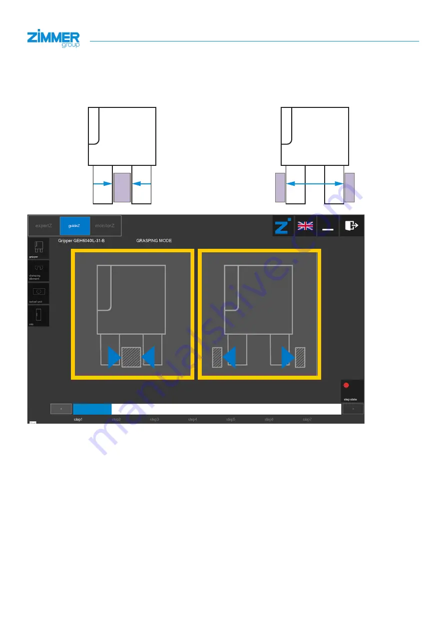
8.4  Selecting the desired gripping direction

Select the required or desired gripping direction (outside or inside gripping).
Depending on the selection, the corresponding appropriate parameters are set in the gripper automatically.

Outside gripping

Inside gripping

Содержание startZ

Страница 1: ...www zimmer group de INSTALLATION AND OPERATING INSTRUCTIONS startZ Universal Robot DDOC01095 THE KNOW HOW FACTORY ...

Страница 2: ...hernet connection 15 7 7 Configuring the IO Link gripper with the SCM 16 8 Commissioning the SCM 17 8 1 Connecting with the SCM 17 8 2 Selecting the gripper in guideZ mode 18 8 3 Switching on the motor and referencing 19 8 4 Selecting the desired gripping direction 20 8 5 Teaching in the workpiece 21 8 6 Setting the workpiece tolerance 22 8 7 Setting the open position 23 8 8 Setting the gripping f...

Страница 3: ...1 30 DDOC01095 0 9 3 8 Controller I O Adjusting the connection assignment 42 9 4 Robot cold start after successful Zimmer installation 47 10 Operation 49 10 1 Zimmer gripper control principle 49 10 2 Overview of generated robot commands 50 10 3 Example of the use of generated robot jobs 52 11 Troubleshooting 52 12 Accessories scope of delivery 52 13 Decommissioning disposal 52 ...

Страница 4: ... lead to serious injury or even death You absolutely must comply with the described measures for avoiding these dangers The warning symbols are assigned according to the type of danger WARNING This notice warns of a situation that is potentially hazardous to personal health Ignoring these notices can cause serious injury or damage to health You absolutely must comply with the described measures fo...

Страница 5: ...duct is used under extreme conditions the maintenance interval must be adapted Use of the product under extreme conditions such as aggressive liquids and abrasive dusts is subject to prior approval from Zimmer GmbH Do not reach into the operational range of the product 3 Proper use NOTICE The product is only to be used in its original state with its original accessories with no unauthorized change...

Страница 6: ... of a maximum of two Zimmer IO Link grippers These grippers must be installed on the tool flange of the robot and connected to the SCM As a rule the following products from Zimmer GmbH can currently be operated If necessary the supplied gripper can therefore be replaced with the products below at any time to suit the application without significantly changing the use Basic IO Link gripper Advanced...

Страница 7: ...IsGripped OnUndefinedPos MotorOn Act_WP_01 IO Link connection cable 5 m M12 connecting cable 5x0 34 max cable length 10 m IO Link digital I O Zimmer Group SCM Comfort App 24 V voltage supply Temporary Ethernet connection Digital I O Robot control system INFORMATION Before actuation of the IO Link gripper by the SCM the gripping application must be trained in the SCM For this purpose download the Z...

Страница 8: ...menkopf 5 77866 Rheinau Germany 49 7844 9138 0 49 7844 9138 80 www zimmer group com 8 EN 2020 11 30 DDOC01095 0 7 Installation 7 1 Installing the hardware components Example depiction of an installed gripper with adapter plate cable and Velcro tape Extension cable M12 5 pin KAG500IL ...

Страница 9: ...y in the event of unexpected movement of the gripper when the power supply is connected Switch off the power supply to the gripper before all work Secure the power supply against being switched on unintentionally Check the power supply for any residual energy NOTICE Switch off the power supply before any assembly installation or maintenance work The gripper must be installed on a mounting surface ...

Страница 10: ... plate 2 Ö 3 0 Nm 1x M4 gripper finger The following work steps must be observed during installation Position the adapter plate 2on the gripper 1 Ö The alignment is carried out using the centering pin 3 Affix the adapter plate 2on the robot using the mounting screws 4 Position the gripper 5on the adapter plate 2 Ö The alignment is carried out using the two centering pins 6 Fix the gripper 5with th...

Страница 11: ...and adapter flange Ö 10 25 Nm 4x M6 mounting screws 4 adapter flange 2 Ö 1 3 Nm 2x M3 gripper finger Ö 6 0 Nm grub screws 8 The following work steps must be observed during installation Unscrew the grub screws 8 Remove the adapter flange 2with the mounting screws 4 Position and align the adapter flange 2using the straight pin 3on the robot 1 Mount the adapter flange 2with the mounting screws 4 Re ...

Страница 12: ...0 www zimmer group com 12 EN 2020 11 30 DDOC01095 0 7 4 Installing the power supply 7 4 1 SCM pin assignment Status Anschluss Ethernet IO Link 1 X1 IO Link 2 X2 Versorgung X3 Status X4 Digital Input X5 X6 Digital Output X7 X8 Versorgung 1 2 3 4 5 6 1 2 3 4 5 6 1 2 3 4 5 6 13 14 15 16 17 18 7 8 9 10 11 12 1 2 3 4 5 6 7 8 9 10 11 12 1 2 3 4 5 6 ...

Страница 13: ...INK_HMI software 1 2 Greifer POWER DI DO 24V E 0 24V E 1 24V S 0 24V S 1 Safety 12V GND ON OFF Remote PWR GND 24V 0V Power 0V 24V D 8 D 9 D 10 D 11 Digital Inputs 24V CI0 24V CI1 24V CI2 24V CI3 Configurable Inputs 24V CI4 24V CI5 24V CI6 24V CI7 0V CO0 0V CO1 0V CO2 0V CO3 Configurable Outputs 0V CO4 0V CO5 0V CO6 0V CO7 24V DI0 24V DI1 24V DI2 24V DI3 Digital Inputs 24V DI4 24V DI5 24V DI6 24V D...

Страница 14: ... strips The respective gripper can now be connected to the SCM using the included cable Ö Then switch on the robot to supply the SCM with power 24V E 0 24V E 1 24V S 0 24V S 1 Safety 12V GND ON OFF Remote PWR GND 24V 0V Power 0V 24V D 8 D 9 D 10 D 11 Digital Inputs 24V CI0 24V CI1 24V CI2 24V CI3 Configurable Inputs 24V CI4 24V CI5 24V CI6 24V CI7 0V CO0 0V CO1 0V CO2 0V CO3 Configurable Outputs 0...

Страница 15: ...Carry out the following points Install the software ZG_IO_LINK_HMI setup on a Windows PC Windows 7 or later Download zimmerDigital urcap in the UR_Comfort_App folder and copy to a USB stick http cloud zimmer group com url zimmerstarzur Password ZimmerStarZUR2020 7 6 Setting up the Ethernet connection Only the lower Ethernet connection green box figure chapter 7 4 1 is active and is connected to a ...

Страница 16: ...e network Click on Set up a new connection or network Ö The connection options appear Click on Set up a new network and follow the instructions on your PC 7 7 Configuring the IO Link gripper with the SCM Configure the IO Link gripper with the SCM in accordance with the following chapter 8 All workpiece recipes must be taught into guideZ in the SCM However at least workpiece recipe no 1 must be ass...

Страница 17: ...ly light up green then status 1 2 flash on the base module as long as the grippers are being searched for depending on the last saved configuration on the SCM 8 1 Connecting with the SCM Connect the computer to the installed Zimmer HMI software ZG_IO_Link_HMI in version 2 0 1 22 or later The three control levels are located at the top left in the software window expertZ Expert level where all grip...

Страница 18: ...f 5 77866 Rheinau Germany 49 7844 9138 0 49 7844 9138 80 www zimmer group com 18 EN 2020 11 30 DDOC01095 0 8 2 Selecting the gripper in guideZ mode Click on the desired gripper to start the guideZ function The following graphic shows a GEH6000 series gripper that is taught to the workpiece ...

Страница 19: ...bar in the lower area of the window On the right in the window the green power supply LED shows whether the actuator voltage is connected Only when the LED lights up green in the bottom right of the window can the button be used to proceed to the next step In this case the gripper motor is still switched off Ö Switch on the motor with one of the two reference run buttons Ö This also references the...

Страница 20: ... 0 49 7844 9138 80 www zimmer group com 20 EN 2020 11 30 DDOC01095 0 8 4 Selecting the desired gripping direction Select the required or desired gripping direction outside or inside gripping Depending on the selection the corresponding appropriate parameters are set in the gripper automatically Outside gripping Inside gripping ...

Страница 21: ...ing the desired gripping direction the operating concept still applies that you can only proceed one step further with the button when the LED in the bottom right of the window lights up green 8 5 Teaching in the workpiece To teach the workpiece parameters into the gripper press and hold the movement buttons in the window on the right The gripper detects the standstill and remembers the workpiece ...

Страница 22: ...www zimmer group com 22 EN 2020 11 30 DDOC01095 0 8 6 Setting the workpiece tolerance For the taught in workpiece the tolerance can be set from 0 00 mm to 2 55 mm Accordingly the gripper automatically sets its closed position just after the workpiece tolerance Ö That is assuming that a servo gripper with freely adjustable positions is being used ...

Страница 23: ...GmbH Im Salmenkopf 5 77866 Rheinau Germany 49 7844 9138 0 49 7844 9138 80 www zimmer group com EN 2020 11 30 DDOC01095 0 8 7 Setting the open position The open position can only be set for grippers with servo functionality Ö Set the position at which the gripper is to be open ...

Страница 24: ...ny 49 7844 9138 0 49 7844 9138 80 www zimmer group com 24 EN 2020 11 30 DDOC01095 0 8 8 Setting the gripping force Provided that the gripper allows it the gripping force can be set In the process the closing speed can also be set automatically INFORMATION Durch die Kraft wird auch die Geschwindigkeit eingestellt ...

Страница 25: ...er GmbH Im Salmenkopf 5 77866 Rheinau Germany 49 7844 9138 0 49 7844 9138 80 www zimmer group com EN 2020 11 30 DDOC01095 0 8 9 Setting the speed for opening the gripper If possible the speed for opening the gripper can be set as desired Ö Only possible for servo grippers ...

Страница 26: ...training for the gripper is ended when the data is saved in the corresponding recipe INFORMATION At this point the set parameters are not yet saved in the corresponding recipe The settings can also be checked without the actual control I Os Input field Ö Click in the blue fields with the mouse to set a command Output field Ö The fields indicate the corresponding status of the gripper Clicking on S...

Страница 27: ...immer GmbH Im Salmenkopf 5 77866 Rheinau Germany 49 7844 9138 0 49 7844 9138 80 www zimmer group com EN 2020 11 30 DDOC01095 0 8 11 Saving the recipe The recipe can now be saved in the SCM Ö Select the desired recipe number and click the save WP button to save the data ...

Страница 28: ...heinau Germany 49 7844 9138 0 49 7844 9138 80 www zimmer group com 28 EN 2020 11 30 DDOC01095 0 8 12 End of saving the data After a successful data save guideZ goes back to Step 1 in order to teach in a new workpiece Ö If this is not intended click on the monitorZ button to switch to observation mode ...

Страница 29: ...30 DDOC01095 0 8 13 monitorZ mode Click on the plug HMI button to transfer the control ability to the digital I O Ö The control LED in the window on the right lights up red It is now no longer possible to control the gripper with the HMI software since the I O signals have now taken over control The gripper can now be moved with the external control system and the saved settings ...

Страница 30: ... zimmer group com 30 EN 2020 11 30 DDOC01095 0 8 14 expertZ mode In expertZ mode it is possible to fine tune the gripping parameters To get full access to all the parameters expertZ fine tuning mode must be switched off Click the service button Ö This opens the Service window In the Application settings area switch off the expertZ fine tuning mode ...
Страница 31: ...77866 Rheinau Germany 49 7844 9138 0 49 7844 9138 80 www zimmer group com EN 2020 11 30 DDOC01095 0 8 15 Testing the gripper with SCM Test each adjustment in expertZ mode first then save the desired recipe again This is the only way to re use the data after a cold start of the SCM from the robot ...

Страница 32: ...N 2020 11 30 DDOC01095 0 9 Commissioning the SCM HMI software 9 1 Switching on the robot 1 First switch on the robot In the Initialize dialog field click the Power OFF LED display and the ON button Once the robot has started up and is in no load operation click the Start button 2 The robot is now in normal mode Click the Exit button to close the Initialize dialog field ...

Страница 33: ... com EN 2020 11 30 DDOC01095 0 9 2 Zimmer Comfort URCap USB stick 1 If the robot is ready insert the USB stick with the Zimmer Comfort URCap 2 In the header select the hamburger menu 3 Select Settings 4 In the menu on the left side click on System and then select URCaps 5 Press the button select the USB connection to display the content and navigate to URCap file ...

Страница 34: ...866 Rheinau Germany 49 7844 9138 0 49 7844 9138 80 www zimmer group com 34 EN 2020 11 30 DDOC01095 0 6 Select the Z_UR_ComfortApp_1 3 0 file and press Open Z_UR_ComfortApp_1 3 0 7 Press Restart to activate the new firmware After the restart the Zimmer GmbH software is installed and ready to use ...

Страница 35: ...r GmbH Im Salmenkopf 5 77866 Rheinau Germany 49 7844 9138 0 49 7844 9138 80 www zimmer group com EN 2020 11 30 DDOC01095 0 8 After the restart check whether the Zimmer GmbH file is installed correctly This requires that the green check is visible in the Active URCaps field ...

Страница 36: ...com 36 EN 2020 11 30 DDOC01095 0 9 3 New gripper configuration 9 3 1 Selecting the connection First select the connection being used Ö To do so select the controller I O for the gripper in the startZ box Then press the next button 9 3 2 Controller I O Number of grippers The number of grippers to which the controller I Os are to be connected must be selected here ...

Страница 37: ...N 2020 11 30 DDOC01095 0 9 3 3 Controller I O Gripper series Advanced must be selected here 9 3 4 Controller I O Command connections Here the robot output number must be made to match the digital SCM input function Ö The wiring must be done exactly according to this screen template Ö If this screen is displayed for the first time some standard assignments are displayed ...

Страница 38: ... assignment is unchanged and the next button is used to continue the following prompt is displayed Confirm with Yes Ö The connection assignment is saved and the next screen for the status connections appears 9 3 5 Controller I O Status connections Here the robot input number must be made to match the digital SCM output function here Ö The wiring must be done exactly according to the screen display...

Страница 39: ...9138 0 49 7844 9138 80 www zimmer group com EN 2020 11 30 DDOC01095 0 Ö The wiring supplied in the startZ box corresponds to the default assignment Ö If the default assignment is unchanged and the next button is used to continue the following prompt is displayed Confirm with Yes Ö The next screen appears for manual operations ...

Страница 40: ...NOTE Ö For this test the robot and SCM must be wired together Furthermore the robot SCM and gripper system must be switched on Ö If necessary the motor must be started with MotorOn The workpiece sets are addressed using the workpiece bit numbers These workpiece bits are available externally as digital I Os of the SCM The desired workpiece must be addressed by setting the workpiece bit numbers The ...

Страница 41: ...and buttons are the toggle buttons that can be switched on and off individually regardless of the other commands Reset MotorOn WP_Bit0 WP_Bit1 WP_Bit2 WP_Bit3 The following command buttons are mutually exclusive If the user selects a button of this group every previously selected button in this group is deselected Grip Release Homing Reset Ö It is possible to navigate back to the connection assign...

Страница 42: ... that the settings are still temporary and should be saved in the installation file The following chapter is only to be used in case of a deviating wiring configuration between the SCM and robot 9 3 8 Controller I O Adjusting the connection assignment Ö If an I O is assigned to a command this is indicated by the green LED display next to the I O button Ö The assignment of a command to an I O is di...

Страница 43: ... to adjust the connection assignment as needed Ö In order to map the command to a controller I O a command button must first be selected e g WP_Bit2 Ö Then press the button of the desired I O CO0 The name of the I O is added to the label of the command button as graphical feedback that the assignment was successful WP_Bit2 CO0 Ö The command is mapped to the controller I Os and can be used both in ...

Страница 44: ...ssignment Ö It is possible to enable the existing command connection assignment as needed Ö To enable the existing command assignment first select the command button e g Reset DO2 Ö Then press the same command button The name of the I O is removed from the label of the command button as graphical feedback that the mapping is enabled e g Reset Ö The command is removed both from the program as well ...

Страница 45: ... g MotorOn DO3 Ö Then press the button of the desired I O e g DO4 The name of the I O is changed to the new I O name in the label of the command button as graphical feedback that the re assignment as successful e g MotorOn DO4 Ö The command is re arranged to the I O of the other controller Ö This can be used both in the program as well as for the manual control Ö The previous I O is not free see D...

Страница 46: ...rd assignment To restore the standard assignment you must return to chapter 9 3 3 Ö The gripper series is changed here and confirmed with next Ö As a result the previous settings for the gripper are deleted Ö You must return to chapter 9 3 3 and repeat the setup steps Ö At this point the gripper can be used in the program node NOTICE Please note that the settings are still temporary and should be ...

Страница 47: ...RCaps on the Installation tab then select Zimmer The following screen is displayed if an available previously made setup is found for two grippers Ö If one of these buttons is selected the screen for manual operation appears Ö Here it is possible to operate the gripper manually and view the status Please note that this screen does not appear if the available setup is only found for one gripper Ö I...

Страница 48: ...7866 Rheinau Germany 49 7844 9138 0 49 7844 9138 80 www zimmer group com 48 EN 2020 11 30 DDOC01095 0 Ö Pressing the delete button brings up the prompt as shown on the following screen Confirm with Yes Ö The existing setup is deleted Ö The screens for the new gripper configuration are displayed ...

Страница 49: ... run if necessary Z_Homing 2 Check if the reference run is OK Z_IsHomingOk or Z_IsHomingSuccess 3 Switch on motor Z_MotorOn 4 Check whether the motor is switched on Z_IsMotorOn 5 If no error Z_IsError prepared Operation A advanced 1 If more than one workpiece is used adjust the workpiece Z_ChangeWp number that was preconfigured with Zimmer IO Link HMI 2 Checking if the workpiece is changed Z_IsWpC...

Страница 50: ...n and ready to grip a workpiece All grippers Z_IsClosed This command checks the status signal IsClosed and sets the result variable Z_IsClosed1_Result for gripper 1 and tool IO gripper or Z_IsClosed2_Result for gripper 2 The result variable is TRUE if the gripper is closed All grippers Z_IsOnTeachPos This command checks the status signal IsGripped and sets the result variable Z_IsOnTeachPos1_Resul...

Страница 51: ...s command can be used to check the result of the Z_Homing command if only the IsError signal is wired with the robot control IO without the IsHomingOk signal of the SCM All advanced grippers The commands Z_ChangeWp or Z_IsWpChanged have additional parameters for setting the required workpiece numbers Ö e g Workpiece profile number two The commands for checking the status have additional options fo...

Страница 52: ...ase contact Zimmer Customer Service if you have any questions 12 Accessories scope of delivery INFORMATION If any accessories not sold or authorized by Zimmer GmbH are used the function of the Zimmer startZ box cannot be guaranteed Zimmer GmbH accessories are specifically tailored to the individual products Optional accessories and those included in the scope of delivery can be found on our websit...

Отзывы: