background image

39

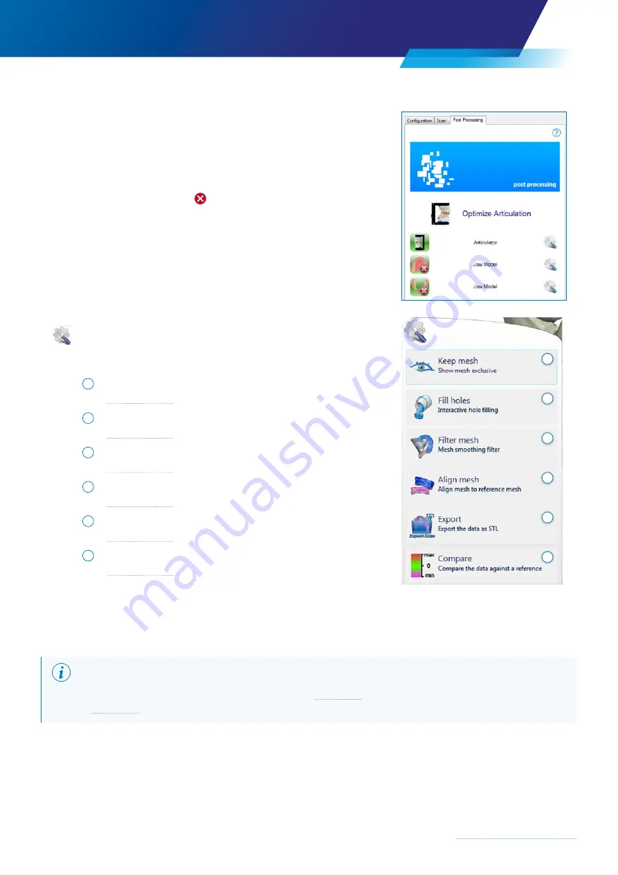
4.6  Operating mode – Post Processing

The Post Processing operating mode assists the user in the subsequent 
processing and preparation of the scan data.

The scanning step can be displayed or hidden by clicking the images. 

If an image is marked with a  , this means that the view is hidden. 


Processing functions are launched by clicking the left mouse button 
on the  

Processing icon 

or the descriptive text.

Possible functions are:

1   Keep mesh 

 see Chapter 4.7.1

2   Fill holes

 see Chapter 4.7.2

3   Filter mesh

 see Chapter 4.7.3

4   Align mesh

 see Chapter 4.7.4

5  Export

 see Chapter 4.7.5

6  Compare

 see Chapter 4.7.6

4.7.1  Keep mesh

By selecting the “Keep mesh” function with the left mouse button, only the individual view of the  
selected scan situation is shown and all other scan situations are hidden. 

NOTE

Refer back for full information on the toolbar functions (

 Chapter 3.4) and the mouse button and keyboard commands 

(

 Chapter 4.2)

1

2

3

4

5

6

Содержание Zfx EvolutionNEXT

Страница 1: ...Zfx EvolutionNEXT Manual A COMPANY OF ...

Страница 2: ... manual and all documents associated with the product to all users of the product Read and follow all safety instructions and Chapter 2 Commissioning Failure to follow these instructions will invalidate the warranty Service and maintenance of the system must be carried out exclusively by technicians staff who have been trained or authorized by Zfx GmbH In the event of any damage in transit read an...

Страница 3: ...quate ventilation for the equipment and do not cover the fan openings CAUTION Do not expose equipment components to rain moisture or heat CAUTION Never replace parts of the scanner with third party components CAUTION Do not use solvents such as nitro sanitary alcohol or grease cleaners CAUTION Do not place objects on the scanner CAUTION Never reach into the area around the positioning unit when th...

Страница 4: ...orage before commissioning 9 1 6 Scope of supply 10 1 6 1 Standard 10 1 6 2 Optional 11 1 7 Purpose Intended use 12 1 7 1 General 12 1 7 2 Product specific information 12 1 7 3 Decommissioning and disposal 12 2 Commissioning 14 2 1 Location 14 2 2 Connecting the system 14 2 3 Electrical connection 14 2 4 Internet connection 15 2 5 Computer 15 2 6 Installing the user software 15 2 7 Switching the u...

Страница 5: ...on of additional restorations 23 4 5 Operating mode Scan 24 4 5 1 User interface Scan mode 24 4 5 2 Scan Assistant Help 24 4 5 3 Define scan area 25 4 5 4 Tooth selection 26 4 5 5 Brightness setting 27 4 5 6 Additional scan in scan step 28 4 5 7 Additional Scan Add Scan 30 4 5 8 Selecting and deleting a data set 31 4 5 9 Alignment of data sets 32 4 5 10 Match holders markers Scan bodies 35 4 6 Ope...

Страница 6: ... 1 Fault finding 51 9 Product description 52 9 1 Datasheet 52 9 1 1 General 52 9 1 2 Electrical connections 52 9 1 3 Desktop power supply 52 9 1 4 Sensors 52 9 1 5 Positioning unit 53 9 1 6 Calibration plate 53 9 1 7 Computer requirements 53 9 2 Device protection 54 9 3 Operating conditions 54 9 4 Ambient conditions transportation and storage 55 9 5 Rating plate 55 9 6 Connecting panel 55 9 7 Oper...

Страница 7: ...7 ...

Страница 8: ...ckaging 1 4 Damage in transit If the packaging is externally damaged on delivery please proceed as follows The recipient must record the loss or damage in the confirmation of receipt The recipient and the shipping company s representative must sign this confirmation of receipt The recipient may only make a claim for compensation worldwide against the shipping company by recording these facts Do no...

Страница 9: ...law Chapter 5 Art 30 1 5 Transportation and storage in the packaging 1 5 1 During transportation and storage up to commissioning The following symbols for transportation and storage must be observed 1 5 2 Storage before commissioning Before commissioning After shipping the system must be left in the packaging for sufficient time for acclimatization so that all components reach the specified operat...

Страница 10: ...1 pcs 4 USB 3 0 connecting cable 1 pcs 5 ZFX02001224 Calibration pedestal for Zfx Evolution 1 pcs 6 ZFX02001225 Spacer plates for Zfx Evolution 1 pcs 7 ZFX02001247 Model base for Zfx Evolution 1 pcs 8 ZFX02001226 Fixator for Zfx Evolution 1 pcs 9 ZFX02002063 Blu Tack adhesive compound 120g 1 pcs 10 ZFX03001034 DELL P3640 Workstation 1 pcs 11 DELL 22 Monitor 1 pcs 12 ZFX03001038 Manual online 1 pcs...

Страница 11: ...onizer Panadent 2 ZFX02001227 Multi Die Table for Zfx Evolution WARNING The operation of active implanted systems e g heart pacemakers defibrillators can be affected by electromagnetic fields Persons with implanted systems must maintain a safety distance of 30cm from the surface of the unit The product complies with the applicable requirements relating to electromagnetic fields in accordance with ...

Страница 12: ... or 3D printers Any use other than that described is considered to be improper use If the Zfx components are integrated into an existing network the responsibility for safety and functionality lies with the network operator CAUTION Never dismantle the sensor unit s cameras or projectors The mechanical positioning of the camera and projector in the sensor unit must be carried out exclusively by Zfx...

Страница 13: ...13 ...

Страница 14: ...y distance of at least 0 25m between the scanner wall and other objects and the user must be maintained to ensure there is no damage to the user and the equipment during the scanning process 2 2 Connecting the system Connect all the cables before commissioning the components Connect the computer to the monitor keyboard and mouse Connect the scanner to the computer by means of the USB cable using t...

Страница 15: ...er software assumes that Zfx Manager 2 0 is installed on the computer From there the scan software can be downloaded installed and activated by means of the product key NOTE Administrator rights are required if an update or new installation are necessary 2 7 Switching the unit on off Only start the scanner once it has reached room temperature Switching on the unit Switch on the socket strip Switch...

Страница 16: ...of the Scan button the user gains access to the Scan operating mode level 4 5 Operating mode Scan 3 1 Glossary RMB Right mouse button MWB Mouse wheel button LMB Left mouse button 3 User interface in standard mode 2 4 5 3 1 1 Menu selection see Chapter 3 1 1 Information display see Chapter 3 3 2 Menu selection see Chapter 3 2 3 Toolbar see Chapter 3 4 4 Operating modes see Chapter 3 5 5 Scan Assist...

Страница 17: ...ts 3 2 4 Calibration The system can be recalibrated The calibration procedure is described in 4 3 Calibration 3 2 5 Service Service mode provides important tools for maintaining and checking the system Service mode is for qualified service personnel only and requires a password How to use the service area is explained in the installation manual which is available separately 3 3 Information display...

Страница 18: ...n of 3D data Rectangle Hold down the Shift key LMB to drag out a rectangle Lasso Hold down the Shift key LMB to define a free form area Select all All 3D data are selected 3 4 3 Delete Delete selection Deletes all selected areas View of the scan object from the side right hand side View of the scan object in a bird s eye view from above View of the scan object in a worm s eye view from below Clear...

Страница 19: ... different operating modes by clicking on the appropriate tab The three different operating modes are described in more detail in the following chapter 1 Configuration see Chapter 4 4 2 Scan see Chapter 4 5 3 Post processing see Chapter 4 6 Light sources Setting in the Properties display Axis of rotation coordinate system The pivot point can be moved from the central position corresponding to the ...

Страница 20: ...s 4 2 Mouse and keyboard commands Mouse button combinations make it easier for the user to process and position the 3D model RMB Rotation in all directions Hold down LMB RMB Move MMB scroll or keep pressed move mouse Enlarge Reduce LMB Zoom window Alt RMB Move clockwise or anticlockwise while displaying the axis of rotation in the direction of view Double click with LMB Positions the scan centrall...

Страница 21: ...er plates Start by clicking the Calibration button Select the connected scanner 1 Confirm the selection by clicking OK 2 NOTE The calibration procedure repeats itself 5 times at different heights 4 3 3 Steps 1 to 5 Calibration plate white 4 Spacer plates 1 mounting plate 1st step Insert the calibration plate with the base plate 1 in the scanner Confirm selection by clicking OK 1 Insert first space...

Страница 22: ...d with a reference data set NOTE The process may take a few minutes please follow the progress status at the bottom of the screen Complete the calibration process by clicking Yes 1 Following calibration the program automatically starts an adjustment process i e the projector setting is checked with reference to the coordinate system Position the calibration plate with a spacer plate and the mounti...

Страница 23: ...nning steps according to the information defined here 4 4 1 Selection of additional restorations Select the tooth the status of which is to be changed with the mouse pointer Clicking the left mouse button opens the menu to enable the newly required status to be selected Reset 1 resets the tooth status NOTE If the tooth status is changed in the configurator a check should be made to ensure that the...

Страница 24: ...o be carried out by left clicking on the Info icon Website The Zfx GmbH website www zfx dental com will be opened Scan 1 Clicking on the jaw model shows the scanning steps necessary for an order see illustration below 2 Clicking the Scan button starts a new scan and gathers 3D data or overwrites existing scan data 3 Additional scan data for a step which has already been scanned can be generated by...

Страница 25: ...ns The arrow buttons allow the user to move forwards or backwards through the scanning steps in order to process the scan order Back The last scan step is discarded Next Complete the scan and go to the next scan step 4 5 3 Define scan area The area that is relevant to the order can be selected in order to narrow down the scope of the scan area top left This helps to save time as areas which are no...

Страница 26: ...scanned for the order are selected in the tooth selection image bottom left It is not absolutely necessary to define the tooth areas the scan can also be carried out without this input However this helps to save time as tooth areas which are not required for calculating the 3D data are no longer considered Under the image the user will find an indication of which of the teeth is to be marked next ...

Страница 27: ...osed The brightness has been set too high 4 5 5 1 Automatic brightness setting The green selection frame allows the user to adjust position and select the area on which the automatic brightness setting is to work The position should be selected such that the area to be scanned is optimally illuminated The optimum brightness for this area is set by double clicking inside the selection frame Reposit...

Страница 28: ...for the object 4 5 6 Additional scan in scan step The Additional Scan function enables the user to interactively influence the result of a scan step e g jaw model The Additional Scan dialog box is displayed after each scan step for this purpose An Additional Scan scan enables missing data to be supplemented by means of one or more additional scans in order to improve the scan result The additional...

Страница 29: ...ace from below If the user should try to make such a setting the rotary swivel unit will automatically set itself to its maximum possible tilting position and indicate this in the 3D display window and the live camera image 2 Camera live image The camera live image shows the position of the model in the unit and can be zoomed by clicking in the window and using the MMB Chapter 4 2 Mouse buttons an...

Страница 30: ...odels the appropriate scan must be restarted from the required point NOTE Only complete the scanning process after carefully checking whether sufficient scan data have been gathered 4 5 7 Additional Scan Add Scan A scan order with for example three specified scan steps jaw model teeth mush bite can be extended by one or more scanning steps using the Add Scan function This function is necessary whe...

Страница 31: ... of data to be stored The less there is the smaller the space required on the storage medium Selection and deletion procedure The area to be scanned is already limited by the scan area setting Chapter 4 5 3 and the tooth selection Chapter 4 5 4 In order to select and delete redundant data the previously scanned step must be selected in the Scan Assistant NOTE It is recommended that the 3D data vie...

Страница 32: ...akes place automatically The user is only required to align data sets manually in cases where automatic alignment is not possible e g in an Add Scan Manual alignment can be carried out using the Align mesh function in the Post Processing operating mode Chapter 4 6 Operating mode Post Processing 4 5 9 1 Alignment interaction window 1 Texture Activate or deactivate the texture of the 3D data model I...

Страница 33: ...is not saved 4 5 9 2 Manual three point alignment When carrying out manual alignment at least three identical points in the two data sets are marked using the Ctrl LMB combination In order to identify three identical points for marking in the two data sets it is expedient to select a similar view for the two data sets As described in Chapter 4 2 Mouse and keyboard commands the views of the two dat...

Страница 34: ...e able to use the automatic precision alignment it is first necessary to mark three identical points Chapter 4 5 9 2 Manual three point alignment The precision alignment of the two data sets is carried out with reference to their object geometry based on this preliminary alignment best fit alignment Align function settings Align function dialog box Information relating to the result of the precisi...

Страница 35: ... created for each tooth angle and coordinate data are accurately measured and transferred to Zfx Manager 2 0 for further processing The uncoded match holders are used as scan bodies and are only measured as such CAUTION Do not modify or contaminate the codes on match holders or render them unrecognizable as this can prevent the markers from being recognized correctly The match holders must be prop...

Страница 36: ...isplayed as such 4 5 10 3 Scanning match holders markers Markers separate The match holder is recorded using the Marker Scan button It can be seen from the green frame whether the marker scan was successful The next scan step is not enabled until the marker has been successfully detected NOTE All match holders that have been set must be marked with a green frame If this is not the case repeat Mark...

Страница 37: ...ing step is increased by the Add Scan function 4 5 10 4 Defining the match holder marker type With coded match holders information relating to the match holder such as tooth marker manufacturer and marker size is shown in the table in the Scan Assistant The system can read this data using the code The exact sub type must be added by the user The exact sub type must be entered separately by the use...

Страница 38: ...he necessary information to the scanning program and displays the Multi Die grid instead of the tooth diagram NOTE The following procedure is recommended Dental Manager Assign the patient s name and tooth number to the respective tooth position on the Multi Die plate Group similar restorations together Scan program The scan procedure is the same as in the chapters already described Scan settings c...

Страница 39: ...cessing icon or the descriptive text Possible functions are 1 Keep mesh see Chapter 4 7 1 2 Fill holes see Chapter 4 7 2 3 Filter mesh see Chapter 4 7 3 4 Align mesh see Chapter 4 7 4 5 Export see Chapter 4 7 5 6 Compare see Chapter 4 7 6 4 7 1 Keep mesh By selecting the Keep mesh function with the left mouse button only the individual view of the selected scan situation is shown and all other sca...

Страница 40: ...ar functions Chapter 3 4 as well as the mouse and keyboard commands Chapter 4 2 remain active The control window in the Fill Hole Assistant is divided into 5 areas 4 7 2 1 Holes In this dialog box the number of holes is listed according to size and number of edges the user can select individual holes 1 Activate or deactivate all holes 2 Number of holes found taking into account size and selection ...

Страница 41: ...e hole geometry is too complex Standard High Highest Additional calculation effort is invested in order to achieve the most homogenous filling possible 3 Resolution Step Description Lowest Reduces the resolution relative to the Standard step by approx Low Reduces the resolution relative to the Standard step by approx 1 Standard The Standard fill resolution is oriented towards the average resolutio...

Страница 42: ...ngs A Keeping the Ctrl key pressed select the two triangles between which a bridge is to be created B Click Apply 6 to accept the bridge and update the hole borders Close the Mesh Bridge dialog box by clicking the Close 7 button C The split hole can then be filled by selecting the hole number Chapter 4 7 2 1 Holes and confirming by clicking the Fill button Chapter 4 7 2 5 Action 4 7 3 Filter mesh ...

Страница 43: ... format 2 Assign a file name 3 Save by clicking the Save button 4 4 7 6 Compare The Compare function enables the user to read data sets from earlier recordings and to compare them with the active data set The function is suitable for example for enabling already machined tooth models to be compared with the source data set Compare procedure Click the Compare button The Explorer window will open Se...

Страница 44: ...n according to the color chart shown Surface color Meaning GREEN Match in the Minimum Error value range no deviation between data sets RED Deviation between data sets which is greater than the positive value of the Maximum Error MAGENTA Deviation between data sets which is greater than the negative value of the Maximum Error The Snapshot 6 button can be used to save the comparison for documenting ...

Страница 45: ...45 ...

Страница 46: ... the accompanying slip The user should ensure that the object to be scanned is positioned securely so that the position of the object does not change when individual model segments are removed The object to be scanned must not protrude at the front beyond the blue perforated sheet 5 Placing the object to be scanned in the scanner Right position Wrong position The object to be scanned is positioned...

Страница 47: ...ocated mounting holes with dental putty and smooth it Press the individual teeth into the putty in such a way that they can be still be easily registered by the scanner 5 3 Zfx Synchronizer Please refer to the operating instructions for the Zfx Synchronizer for carrying out alignment in the synchronizer Lock the whole Zfx Synchronizer into place on the rotary swivel unit Right position Wrong posit...

Страница 48: ...g the scan 3 Scan object Place the object to be scanned in the scanner 5 Placing the object to be scanned in the scanner 4 Adjust the brightness Determine the optimal illumination for the scanning area 4 5 5 Brightness setting 5 Define the scanning area Select the scanning area by adjusting the frame 4 5 3 Defining the scan area 6 Tooth selection Select the scanning area with the position circle 4...

Страница 49: ...eady gathered at the time the scan is aborted is automatically saved in the patient file created with Zfx Manager 2 0 6 5 Restarting an aborted scan order An already existing scan order can be restarted at a later stage The data stored in the patient file is reloaded automatically into the scan program from Zfx Manager 2 0 1 Start Zfx Manager 2 0 2 Open the patient file 3 Start the scan program us...

Страница 50: ...st be used CAUTION Do not use solvents such as nitro sanitary per alcohol or grease cleaners Never adjust or turn the aperture rings of the camera and projector Do not clean the projector and camera lenses as this may damage the objective lenses 7 2 Regular measures Wipe away contamination with a damp cloth without detergent Wipe the outer housing with a fine duster CAUTION Do not use compressed a...

Страница 51: ...hat minimum distance from wall is 0 25 m If appropriate avoid direct sunlight Fuse blown Condensation Short circuit When replacing the fuse follow the instructions in Chapter 9 2 Sensor unit out of adjustment The sensor unit can go out of adjustment if the working temperature differs significantly from 15 C to 30 C Calibration shows a strong deviation in accuracy Always wait until the device has r...

Страница 52: ...If the cable for the desktop power supply becomes damaged replace it immediately To do this contact Zfx Support 9 1 4 Sensors Camera sensor technology Color CCD USB 3 1 Camera resolution 2 2 048 1 536 pixels Protection unit DLP display size 1 200 800mm2 Light source LED RGB max 48W Number of projected line pairs 128 Minimum measuring time ms 980 Triangulation angle 20 Base length mm 85 Operating d...

Страница 53: ...hieved under defined measuring conditions and following precision calibration of the sensor They apply exclusively in combination with a system configuration supplied by Zfx All accuracy figures may be dependent on the surface of the object and environmental conditions 1 All values listed in this datasheet are average values within defined tolerances They give an idea of the order of magnitude For...

Страница 54: ...the fuse symbol See Chapter 9 6 Connecting panel Use a flat screwdriver to open the fuse holder 9 3 Operating conditions Permissible ambient temperature range 15 C to 30 C Permissible up to max relative humidity 80 Permissible up to max ASL 2 000m For indoor use only 1 2 WARNING Only qualified personnel who have first read and understood the above instructions are allowed to change electronic fuse...

Страница 55: ...Meaning Unit type Zfx EvolutionNEXT Item number Serial number VOLTAGE Supply voltage POWER Power Caution Read the instruction manual CE mark Disposal information see Intended use Manufacturer 9 6 Connecting panel The connecting panel can be found on the rear of the unit Symbol Meaning 1 On Off switch Fuse 2 Operating lamp DC USB port 9 7 Operating lamp The operating lamp shows the operating state ...

Страница 56: ...d in Chapter 4 5 appears Scanning procedure The user can again check the scan order created in Zfx Manager 2 0 or if necessary add a restoration in the configurator NOTE Not all Dental Manager programs are compatible with the additional configuration please always check that the Dental Manager has accepted the restoration created using the configurator Three steps are necessary for the chosen exam...

Страница 57: ...ght arrow button The user can now decide whether to gather further data Confirm by clicking the Additional Scan dialog button the additional scan will be started Chapter 4 5 6 Additional scan in scan step Additional Scan If an additional scan is unnecessary as all relevant data have been gathered complete the process by clicking the right arrow button The program automatically jumps to the next st...

Страница 58: ...al Scan If an additional scan is unnecessary as all relevant data have been gathered complete the process by clicking the right arrow button The program automatically jumps to the next step NOTE If the data from step 1 and step 2 cannot be correlated automatically e g due to the model moving on the mounting plate then the user will be prompted to align the data sets Chapter 4 5 9 Alignment of data...

Страница 59: ...marker recognition was successful by the green frame around the marker and the display of the marker type If both conditions are met the right arrow button will be enabled and the user can start the scan Start the scan by clicking the right arrow button The user can now decide whether to gather further data Confirm by clicking the Additional Scan dialog button the additional scan will be started C...

Страница 60: ...nts rotation No lock turns freely does not prevent rotation TI Base hybrid abutment consisting of a titanium base with an attached body section Scanning process complete all necessary data have been gathered The user can select and delete superfluous data Chapter 4 5 8 Selecting and deleting a data set NOTE All images in the Scan Assistant are green i e 3D data have been gathered in each scanning ...

Страница 61: ...eth Teeth 12 21 and 15 17 Select antagonist type Virtual articulator Save order Start scan by clicking the Scan button The scan program is started by clicking the scan button in Zfx Manager 2 0 The user interface for scanning mode as described in Chapter 4 5 Operating mode Scan appears Step 1 3 Whole jaw model scan Insert the Zfx Synchronizer with the full jaw model fitted See the description of t...

Страница 62: ...al Scan If an additional scan is unnecessary as all relevant data have been gathered confirm by clicking the right arrow button The data are recalculated and summarized in a 3D data set This process takes a few seconds please check the progress bar When the data have been gathered the program automatically advances to the next step Step 2 3 Upper jaw scan It is not necessary to switch to the next ...

Страница 63: ...lts more easily Chapter 4 5 5 If an additional scan is unnecessary as all relevant data have been gathered confirm by clicking the right arrow button The user will be prompted to align the data sets Chapter 4 5 9 Alignment of data sets Confirm the alignment by clicking OK The program calculates the necessary data and goes automatically to the next step Step 3 3 Lower jaw scan It is not necessary t...

Страница 64: ...thered confirm by clicking the right arrow button The program calculates the necessary data and all steps are marked as complete in the Scan Assistant If superfluous data are to be removed the user can select the data at the end or after each step Data set selection and deletion can be started Chapter 4 5 8 Selecting and deleting a data set NOTE All recorded data sets can be displayed and edited a...

Страница 65: ...65 ...

Страница 66: ...1117DE REV 10 21 2021 Zfx GmbH Zfx GmbH Kopernikusstraße 15 85221 Dachau Germany Tel 49 81 31 33 244 0 Fax 49 81 31 33 244 10 info zfx dental com www zfx dental com A COMPANY OF ...

Отзывы: