background image

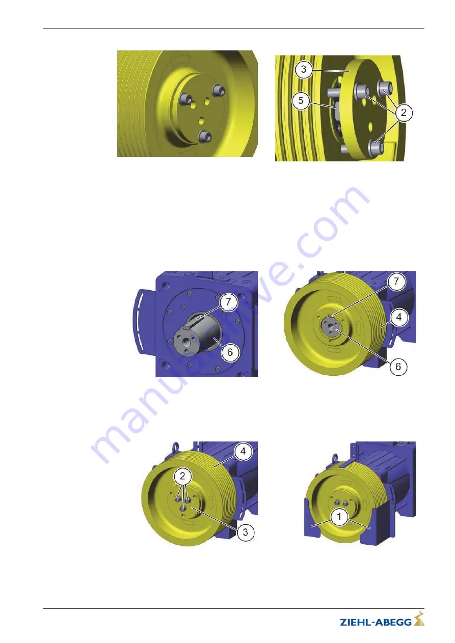
3. Turn the front plate (3) to press off.

4. 5 - 8 mm spacer or hexagon nut (5) must be placed between shaft end and front plate (3).

5. Screw4front plate( ) to the traction sheave (4) at the outer circle of holes using hex socket screws

M16 x 50 (2).

6. Tighten the screws M16 x 50 (2) uniformly with an allen wrench SW 14 By tightening the screws

the tractions sheave (4) will be pulled from the drive shaft.

8.3.3.3

Mounting the traction sheave

The mounting kit (article 70029992) can be used to mounting the traction sheave. This is optionally 

available.

1. Clean the traction sheave (4) and drive shaft (6) with a micro-active cloth and quick cleaner. Both

parts must be free of dirt, grease and rust.

2. The parallel key (7) has to be available.

3. Put  traction  sheave  (4)  on  drive  shaft  (6).  The  bores  for  screws  M16  must  point  outwards.

Observe the position of the groove for the parallel key.

4. Screw the front plate (3) onto the drive shaft (6) at the inner hole circle using the three hex socket

screws M16 x 50 (2). Apply screw threadockerLoctite 243 or a similar product to the 

xing

screws.

Do not forget spring washers!

Translation of the original operating instructions

 ZAtop


 model series SM210.60B/SM210.70B

Service and maintenance

$7%$B*%

,QGH[

Part.-No. 01013389-GB (EU-BD 1014)

39/88

Содержание ZAtop SM210.60

Страница 1: ... 7 B QGH UW 1U 8 WRS 60 60 60 60 HDUOHVV SHUPDQHQW PDJQHW V QFKURQRXV PRWRU 2ULJLQDO RSHUDWLQJ LQVWUXFWLRQV 6WRUH IRU IXWXUH XVH ...

Страница 2: ...stening rope guard 12 4 5 1 Rope guard fastening in the case of a traction sheave diameter of 240 mm 13 4 5 2 Rope guard fastening in the case of a traction sheave diameter of 320 mm 13 4 5 3 Rope guard fastening in the case of a traction sheave diameter of 320 mm and 400 mm 14 4 5 4 Rope guard fastening in the case of a traction sheave diameter of 520 mm 14 4 6 Patent situation 15 5 Electrical in...

Страница 3: ...ncoder ECN1313 ERN1387 26 8 3 1 1 Required tool for the replacement of the absolute encoder 26 8 3 1 2 Dismounting the absolute encoder 27 8 3 1 3 Pre assembly of the absolute value encoder 28 8 3 1 4 Mounting the absolute encoder 29 8 3 2 Replacement of the brake 30 8 3 2 1 Required tool for the replacement of the brake 31 8 3 2 2 Dismounting the brake 31 8 3 2 3 Mounting the brake 34 8 3 2 4 Fun...

Страница 4: ...tment of the release monitor with microswitch 66 9 4 2 Assembly and adjustment of the release monitor with inductive proximity switch 68 9 5 EU Declaration of Conformity for Brake 70 9 6 EC Type Examination Certificate 72 9 6 1 Statement on type examination certificates 77 9 7 Calculation of tripping speed 77 9 8 Calculation proof 78 9 9 Calculation proof 81 Translation of the original operating ins...

Страница 5: ...e operating instructions may be neither completely nor partially photocopied reproduced translated or put on a data medium without prior explicit consent from ZIEHL ABEGG SE Infringements are liable for damages All rights reserved including those that arise through patent issue or registration on a utility model 2 Safety instructions 2 1 General The ZIEHL ABEGG SE elevator machine is not a ready t...

Страница 6: ...for these jobs Based on their training knowledge and experience as well as knowledge of the relevant stand ards they must be able to judge the work transferred to them and be able to recognize possible hazards In addition they must be knowledgeable about the safety regulations EU directives rules for the prevention of accidents and the corresponding national as well as regional and in house regula...

Страница 7: ... short circuit a short circuit current of at least the level of the rated current is flowing The windings may not be short circuited when the elevator machine is energised Safety features for example the brake release monitoring may not be dismantled circumvented or made inoperative Thermistor installed in the winding act as protection against excess temperatures in the elevator machine and must be...

Страница 8: ...esigned as a gearless elevator machine for traction sheave rope elevators Owing to its very compact design the ZAtop SM210 60B SM210 70B is ideal for machine roomless elevators The type tested brake can be used as a Brake mechanism acting on the drive shaft as part of the ascending car overspeed protection means Brake element acting on the drive shaft as part of the protection against unintended c...

Страница 9: ...ote The first rated currrent is the decisive factor in the selection of both the frequency inverter and the line cross section of the motor cable 3 3 Transport ZIEHL ABEGG SE elevator machine are packed by the manufacturer for the types of transport and storage agreed upon Position of eyelets Transport the elevator machine either with the original packing or at the casted eyelets or eyebolts using ...

Страница 10: ... the rotor to any heavy mechanical shocks Before starting installation the elevator machine must be checked for transport damage especially the cables have to be checked No welding must be carried out on the elevator machine The elevator machine must not be used as an earthing point for welding Magnets and bearings could be destroyed The cooling airflow around the elevator machine must not be obstr...

Страница 11: ...heave either centred or towards the motor side 4 4 Rope pull The rope pull must be vertical to the motor foot The rope force direction resulting from rope pull must be observed Resulting rope force Translation of the original operating instructions ZAtop model series SM210 60B SM210 70B Mechanical installation 7 B QGH Part No 01013389 GB EU BD 1014 11 88 ...

Страница 12: ...ird rope retainer 2 is optionally available Set the rope guard to a distance of 2 3 mm from the ropes Rope guard adjustability Depending on the rope guard design the rope pull can be adjusted differently For wrap angle 180 Adjustability on both sides 5 Normal wrap angles 175 185 Adjustability on both sides 5 30 Normal wrap angles 150 185 Translation of the original operating instructions ZAtop mod...

Страница 13: ...uard fastening in the case of a traction sheave diameter of 320 mm For wrap angle 180 Rope guard in the case of a traction sheave diameter of 320 mm Third rope retainer optional with traction sheave diameter 320 mm The rope guard 1 is fastened to the bearing bracket with two hexagon head screws M8 x 16 8 8 3 and washers 4 in each case The slotted hole in the rope guard 1 enables the required dista...

Страница 14: ...6 Tightening torque M8 8 8 23 Nm 4 5 4 Rope guard fastening in the case of a traction sheave diameter of 520 mm Adjustability on both sides 5 30 Normal wrap angles 150 185 Rope guard in the case of a traction sheave diameter of 520 mm The rope guard 1 is fastened to the relevant fixing plate 3 with two safety screws M6 x 12 8 8 4 in each case The elongated hole in the fixing plate 3 enables the requ...

Страница 15: ...is only allowed for authorized persons using a key or special tool Never clean electrical equipment with water or similar liquids 5 2 EMC directive Compliance with the EMC directive 2004 108 EG only applies to this product if frequency inverters tested and recommended by ZIEHL ABEGG SE are used and they are installed in line with the associated operating instructions and are EMC compatible If this...

Страница 16: ...ond to the selected direction the turning direction of the elevator machine must be changed in the frequency inverter configuration If the motor line is not connected to the correct phase control of the elevator machine is not possible It can result in jerky movements or uncontrolled acceleration of the elevator machine 1 Frequency inverter 2 Motor temperature monitoring 5 3 6 Temperature monitorin...

Страница 17: ...Cable length Cable length maximum 25 m Shielded twisted pair cable 5 4 2 Contact assignment SV120 circular connector to absolute value encoder ECN1313 ZIEHL ABEGG SE Standard Pin Signal Designation A DATA Data line for communication with the absolute encoder B DATA Data line inverse C 5 V Sensor Up Sensor cable for encoder voltage 5 V positive D 5 V Up Controlled 5 V voltage supply positive E 0 V ...

Страница 18: ... circuits can be opened separately with mechanical hand release 5 5 3 Release monitoring The brake release monitoring serves as monitoring for redundancy and the operation status of the brakes Release monitoring for the brakes is carried out by a microswitch or inductive proximity switch For technical data see chapter Appendix Technical data Microswitch or inductive proximity switch 5 5 4 Control ...

Страница 19: ...or machine and mounted on site for a better attainability The brake is only allowed to be supplied with power when fastened to the motor and after having connected the protective conductor of the motor at the control and the motor side The brakes have to be protected against over voltage from switching by varistors The brakes are supplied with varistors ex factory Translation of the original opera...

Страница 20: ...m strength 2 mA DC 4 Operating voltage range 10 30 V DC 5 Shown with currentless brake 5 6 Forced cooling The forced ventilation is optional and can be added afterwards 5 6 1 Technical data Voltage 220 240 V Frequency 50 60 Hz Power 50 50 W Current 0 24 0 23 A Translation of the original operating instructions ZAtop model series SM210 60B SM210 70B Electrical installation 7 B QGH Part No 01013389 ...

Страница 21: ... Tests Tests on elevator systems can be performed by the assembly company or a certification authority or organisation This involves discovering of failure critical and hazardous conditions The relevant operator is responsible for safety The descriptions below are intended as recommendations for the technical procedure and do not deal in sufficient depth with safety engineering aspects of the releva...

Страница 22: ... switches The release monitoring for the brakes must be evaluated Before every trip the change in the state of both brake circuits must be monitored separately Switching must thus be tested individually according to the function as an NC and or NO contact If there is a missing or incorrect signal the elevator cabin may not leave the stopping point 6 4 Pull out of safety gear If the car loaded with...

Страница 23: ...e monitored closely during evacuation and evacuation interrupted if necessary Releasing of the brake can be ended when a floor is reached Now the elevator door can be opened with a triangular key The elevator manufacturer s safety instructions have priority 6 5 2 Releasing of the brake with the lever for hand release A brake with a mechanical hand release system is available optionally The hand rel...

Страница 24: ...tching for nor mal operation Fit an additional protective circuit Air gap of brake too big Replacing the brake blocks Brake does not re lease Power supply too low The voltage at the brake is to low Check supply if necessary increase cable cross section and transformer Brake control wrong defective Check brake control Brake coil defective Replace brake special tool required ZIEHL ABEGG SE Contact c...

Страница 25: ...t be free of damage x x Check the traction sheave if worn out x Note All fixing screws on the housing brakes and traction sheave are marked with locking varnish That means a loosened screw is optically visible If a screw does get turned it must be tightened using the prescribed tightening torque the old locking varnish needs to be removed and marking has to be made again 8 2 1 Checking the air gap ...

Страница 26: ... 3 Traction sheave 4 Rope guard 5 Rope retainer 6 Forced cooling 8 3 1 Replacement of the absolute encoder ECN1313 ERN1387 The absolute encoder is mounted on the motor drive shaft opposite the power take off side see arrow Position of absolute encoder 8 3 1 1 Required tool for the replacement of the absolute encoder Wire cutter Allen wrench SW 2 Allen wrench SW 4 Torque wrench for tightening torqu...

Страница 27: ...ral encoder fastening screw 4 thus releasing the absolute value encoder 6 Unscrew the screw M10 x 25 5 again 7 Unscrew the central encoder fastening screw 4 with the size 4 Allen key 8 Screw the screw M10 x 25 5 onto the absolute encoder again and use the screw to remove the absolute encoder Caution Due the electrostatic discharge the absolute encoder can be destroyed Do not touch the pins of the ...

Страница 28: ...Caution Due the electrostatic discharge the absolute encoder can be destroyed Do not touch the pins of the encoder cable as well as the electronics of the absolute encoder You must discharge your own body before touching This can be done for example by touching a conductive earthed object e g bare metal switch cabinet parts immediately before Translation of the original operating instructions ZAto...

Страница 29: ...This can be done for example by touching a conductive earthed object e g bare metal switch cabinet parts immediately before 1 The brake is used to centre the absolute encoder 2 Insert the absolute value encoder into the housing with a slight turning motion 3 Tighten the central encoder fastening screw 4 with the size 4 Allen key Tightening torque 5 0 5 Nm 4 Align the cable outlet by rotating the a...

Страница 30: ...g also the operating manual of the brake has to be observed Risk of death When dismounting the brake make sure that the cabin and the counterweight are mechanically secured against movement Risk of death Incorrect mounting can have a detrimental impact on the braking action The brake is mounted opposite the power take off side see arrow Brake with mechanical hand release system Translation of the ...

Страница 31: ...hapter Replacement of the absolute encoder Wire cutter Cable stripper Crimper Slotted screwdriver 0 6 x 3 5 screw wrench SW 13 screw wrench SW 24 Torque wrench for tightening torque 183 Nm with SW 24 screw wrench SW 32 Allen key SW 17 Torque wrench for a tightening torque of 60 Nm with allen wrench SW 17 Wrench included in toolkit article 70027450 Assembly shaft included in toolkit article 7002745...

Страница 32: ...8 7 using a screw wrench SW 13 and remove the fixing plate 6 9 Dismount the absolute encoder 8 see chapter Replacement of the absolute encoder 10 Unscrew adapter shaft 9 from the motor shaft with wrench 10 and screw wrench SW 32 Translation of the original operating instructions ZAtop model series SM210 60B SM210 70B Service and maintenance 7 B QGH Part No 01013389 GB EU BD 1014 32 88 ...

Страница 33: ...step by step procedure using a screw wrench SW 24 14 Take off the brake body 13 ATTENTION Weight of the brake body is approx 90 kg 15 Remove the brake rotor 14 from the toothed motor shaft The brake rotor may only be removed manually ATTENTION Do not work with screwdrivers to loosen the brake rotor The friction lining can be damaged by the screwdrivers Brake discs with damaged friction linings may...

Страница 34: ...19 4 Wire end sleeves 20 1 Micro active cloth 21 1 Feeler gauges 13 part 22 1 Thread locking fluid 20 ml 23 1 Technical vaseline 50 g 24 1 Quick cleaner LOCTITE 7063 400 ml The assembly kit article 70029992 including nos 4 and 19 to 24 is optionally available and supplied in a separate folding box Translation of the original operating instructions ZAtop model series SM210 60B SM210 70B Service and ...

Страница 35: ...y from the machine wall 4 Make sure that the gear teeth engage easily 5 O ring may not be damaged 6 Caution Due to the great weight of the brake body we recommend you to secure and change the brake body by using an eye bolt M12 A and appropriate lifting gear 7 Push the brake body 13 onto the assembly shaft 11 ATTENTION Weight of the brake body approx 90 kg 8 Apply threadlocker Loctite 243 to the h...

Страница 36: ...mature disk when de energised Air gap 0 4 mm A 0 65 mm This air gap must be present in the area of the vertical central axis of both armature disks 19 See the brake operating instructions in the appendix 15 Check air gap B 0 25 mm between the brake rotor and armature disk when energised The test air gap must be present See brake operating instructions in the appendix If the air gaps are outside th...

Страница 37: ...prevent the actuation of the micro switches inductive proximity switches see chapter Brake operating instructions release monitor in the appendix The micro switches inductive proximity switches will otherwise have to be readjusted see the chapter Assembly and adjustment of release monitor with micro switches or inductive proximity switches in the appendix 8 3 2 5 Adjustment of the microswitch indu...

Страница 38: ...ired tools for the replacement of the traction sheave Allen wrench SW 14 Torque wrench for a tightening torque of 195 Nm with allen wrench SW 14 5 8 mm spacer or hexagon nut 8 3 3 2 Dismounting the traction sheave 1 Remove rope guard 1 see chapter Mechanical installation fastening of rope guard 2 Release the fixing screws M16 x 50 2 of the traction sheave 4 with an allen wrench SW 14 and remove the...

Страница 39: ...y available 1 Clean the traction sheave 4 and drive shaft 6 with a micro active cloth and quick cleaner Both parts must be free of dirt grease and rust 2 The parallel key 7 has to be available 3 Put traction sheave 4 on drive shaft 6 The bores for screws M16 must point outwards Observe the position of the groove for the parallel key 4 Screw the front plate 3 onto the drive shaft 6 at the inner hol...

Страница 40: ...unting and dismounting of the magnet rotor and the flange bearing bracket must only be carried out by qualified personnel and with special devices in the factory Warning The drawbars of the elevator machine must not be released under any circumstances 8 3 5 Retrofittiing the forced ventilation 8 3 5 1 Required tools for the retrofitting of the forced ventilation Screw wrench SW 19 8 3 5 2 Scope of del...

Страница 41: ...of 3 Nm into the intended thread A A exceeding of the tightening torque leads to the damage of the thermostat switch 8 3 5 4 Mounting of the forced ventilation 1 Unscrew eye bolt M12 B from the housing 2 Fasten the pre mounted forced ventilation 1 onto the motor housing with hexagon head screw M12 x 20 8 8 2 and eye bolt M12 B 3 Feed the insulating hose of the thermostat into the terminal box 4 At...

Страница 42: ...tal weight witout traction sheave kg 435 456 Traction sheave Diameter mm 320 400 320 400 Width mm 150 150 150 150 Rope diameter mm 8 10 8 10 Standard number of grooves 8 8 10 8 Standard groove distance mm 17 17 14 17 Table shows typical data other values possible Other rope diameters and groove distances are possible Dependent on travel compensation ropes may be necessary 9 1 1 Protection rating C...

Страница 43: ... power W 158 Electrical protection rating IP 54 Mechanical protection rating IP 10 9 1 3 1 Micro switch Minimum rating mA V 10 12 Maximum rating A V 3 250 Recommended rating mA V 10 50 24 9 1 3 2 Inductive proximity switch Operating voltage VDC 10 30 Rated operating current mADC 150 Output function NC contact gauge zero For further information refer to the Appendix Brake operating instructions Ass...

Страница 44: ...Dimension sheet 9 2 1 Dimension sheet ZAtop SM210 60 SM210 70 Translation of the original operating instructions ZAtop model series SM210 60B SM210 70B Enclosure 7 B QGH Part No 01013389 GB EU BD 1014 44 88 ...

Страница 45: ...9 2 2 Dimension sheet ZAtop SM210 60B SM210 70B Translation of the original operating instructions ZAtop model series SM210 60B SM210 70B Enclosure 7 B QGH Part No 01013389 GB EU BD 1014 45 88 ...

Страница 46: ... 9 3 EC EU declaration of conformity Translation english A KON16_02 GB 1612 Index 001 Manufacturer ZIEHL ABEGG SE Heinz Ziehl Straße 74653 Künzelsau Germany The manufacturer shall bear sole responsibility for issuing this EC EU declaration of conformity Product description ZAtop Gearless elevator machine Type SM132 SM180 SM210 The type specifications contain further additions for different versions...

Страница 47: ...dards have been used EN 12015 2014 Electromagnetic compatibility Productfamily standard for elevators escalators and moving walks Emission This declaration relates exclusively to the product in the state in which it was placed on the market and excludes components which are added and or operations carried out subsequently by the final user The authorised representative for the assembly of the techn...

Страница 48: ...9 4 Operating instructions brake Translation of the original operating instructions ZAtop model series SM210 60B SM210 70B Enclosure 7 B QGH Part No 01013389 GB EU BD 1014 48 88 ...

Страница 49: ...Translation of the original operating instructions ZAtop model series SM210 60B SM210 70B Enclosure 7 B QGH Part No 01013389 GB EU BD 1014 49 88 ...

Страница 50: ...Translation of the original operating instructions ZAtop model series SM210 60B SM210 70B Enclosure 7 B QGH Part No 01013389 GB EU BD 1014 50 88 ...

Страница 51: ...Translation of the original operating instructions ZAtop model series SM210 60B SM210 70B Enclosure 7 B QGH Part No 01013389 GB EU BD 1014 51 88 ...

Страница 52: ...Translation of the original operating instructions ZAtop model series SM210 60B SM210 70B Enclosure 7 B QGH Part No 01013389 GB EU BD 1014 52 88 ...

Страница 53: ...Translation of the original operating instructions ZAtop model series SM210 60B SM210 70B Enclosure 7 B QGH Part No 01013389 GB EU BD 1014 53 88 ...

Страница 54: ...Translation of the original operating instructions ZAtop model series SM210 60B SM210 70B Enclosure 7 B QGH Part No 01013389 GB EU BD 1014 54 88 ...

Страница 55: ...Translation of the original operating instructions ZAtop model series SM210 60B SM210 70B Enclosure 7 B QGH Part No 01013389 GB EU BD 1014 55 88 ...

Страница 56: ...Translation of the original operating instructions ZAtop model series SM210 60B SM210 70B Enclosure 7 B QGH Part No 01013389 GB EU BD 1014 56 88 ...

Страница 57: ...Translation of the original operating instructions ZAtop model series SM210 60B SM210 70B Enclosure 7 B QGH Part No 01013389 GB EU BD 1014 57 88 ...

Страница 58: ...Translation of the original operating instructions ZAtop model series SM210 60B SM210 70B Enclosure 7 B QGH Part No 01013389 GB EU BD 1014 58 88 ...

Страница 59: ...Translation of the original operating instructions ZAtop model series SM210 60B SM210 70B Enclosure 7 B QGH Part No 01013389 GB EU BD 1014 59 88 ...

Страница 60: ...Translation of the original operating instructions ZAtop model series SM210 60B SM210 70B Enclosure 7 B QGH Part No 01013389 GB EU BD 1014 60 88 ...

Страница 61: ...Translation of the original operating instructions ZAtop model series SM210 60B SM210 70B Enclosure 7 B QGH Part No 01013389 GB EU BD 1014 61 88 ...

Страница 62: ...Translation of the original operating instructions ZAtop model series SM210 60B SM210 70B Enclosure 7 B QGH Part No 01013389 GB EU BD 1014 62 88 ...

Страница 63: ...Translation of the original operating instructions ZAtop model series SM210 60B SM210 70B Enclosure 7 B QGH Part No 01013389 GB EU BD 1014 63 88 ...

Страница 64: ...Translation of the original operating instructions ZAtop model series SM210 60B SM210 70B Enclosure 7 B QGH Part No 01013389 GB EU BD 1014 64 88 ...

Страница 65: ...Translation of the original operating instructions ZAtop model series SM210 60B SM210 70B Enclosure 7 B QGH Part No 01013389 GB EU BD 1014 65 88 ...

Страница 66: ...Assembly and adjustment of the release monitor with microswitch Translation of the original operating instructions ZAtop model series SM210 60B SM210 70B Enclosure 7 B QGH Part No 01013389 GB EU BD 1014 66 88 ...

Страница 67: ...Translation of the original operating instructions ZAtop model series SM210 60B SM210 70B Enclosure 7 B QGH Part No 01013389 GB EU BD 1014 67 88 ...

Страница 68: ... and adjustment of the release monitor with inductive proximity switch Translation of the original operating instructions ZAtop model series SM210 60B SM210 70B Enclosure 7 B QGH Part No 01013389 GB EU BD 1014 68 88 ...

Страница 69: ...Translation of the original operating instructions ZAtop model series SM210 60B SM210 70B Enclosure 7 B QGH Part No 01013389 GB EU BD 1014 69 88 ...

Страница 70: ...9 5 EU Declaration of Conformity for Brake Translation of the original operating instructions ZAtop model series SM210 60B SM210 70B Enclosure 7 B QGH Part No 01013389 GB EU BD 1014 70 88 ...

Страница 71: ...Translation of the original operating instructions ZAtop model series SM210 60B SM210 70B Enclosure 7 B QGH Part No 01013389 GB EU BD 1014 71 88 ...

Страница 72: ...9 6 EC Type Examination Certificate Translation of the original operating instructions ZAtop model series SM210 60B SM210 70B Enclosure 7 B QGH Part No 01013389 GB EU BD 1014 72 88 ...

Страница 73: ...Translation of the original operating instructions ZAtop model series SM210 60B SM210 70B Enclosure 7 B QGH Part No 01013389 GB EU BD 1014 73 88 ...

Страница 74: ...Translation of the original operating instructions ZAtop model series SM210 60B SM210 70B Enclosure 7 B QGH Part No 01013389 GB EU BD 1014 74 88 ...

Страница 75: ...Translation of the original operating instructions ZAtop model series SM210 60B SM210 70B Enclosure 7 B QGH Part No 01013389 GB EU BD 1014 75 88 ...

Страница 76: ...Translation of the original operating instructions ZAtop model series SM210 60B SM210 70B Enclosure 7 B QGH Part No 01013389 GB EU BD 1014 76 88 ...

Страница 77: ... 67 3 07 SM200 15C SM200 30C 210 510 587 5 61 6 45 2 80 3 22 SM200 15C SM200 30C 240 510 587 6 41 7 37 3 20 3 69 SM200 15C SM200 30C 320 510 587 8 55 9 83 4 27 4 91 SM200 15C SM200 30C 400 510 587 10 68 12 28 5 34 6 14 SM200 15C SM200 30C 450 510 587 12 02 13 82 6 01 6 91 SM200 40C 160 300 345 2 51 2 89 1 26 1 45 SM200 40C 200 300 345 3 14 3 61 1 57 1 81 SM200 40C 210 300 345 3 30 3 79 1 65 1 90 S...

Страница 78: ...haft hub connections by IFF ENGINEERING CONSULTING GmbH No 7 1 508 3 vom 05 04 2017 Examination basis DIN 743 1 2012 12 Calculation of load capacity of shafts and axles Part 1 General DIN 743 2 2012 12 Calculation of load capacity of shafts and axles Part 2 Theoretical stress concentration factors and fatigue notch factors DIN 743 3 2012 12 Calculation of load capacity of shafts and axles Part 3 S...

Страница 79: ... 2 kN Distance from bearing A to centre traction sheave a 122 mm Rated torque Tr 850 Nm TT Tmax 1600 Nm Magnetic force FMag 3130 N Nominal brake torque TBr 2400 Nm Maximum brake torque 2 x TBr 4800 Nm Rated speed nr 400 U min Examination result For the examination a calculation of traction sheave shaft including shaft hub connections was carried out by IFF ENGINEERING CONSULTING GmbH The result wa...

Страница 80: ... the traction sheave shaft Künzelsau 07 04 2017 place and date of issue ZIEHL ABEGG SE Roland Hoppenstedt Head of R D Drive Division name function ZIEHL ABEGG SE André Lagies Manager R D Mechanics Drive Division name function signature signature Translation of the original operating instructions ZAtop model series SM210 60B SM210 70B Enclosure 7 B QGH Part No 01013389 GB EU BD 1014 80 88 ...

Страница 81: ...culation of load capacity of shafts and axles Part 3 Strenght of materials DIN 743 3 Corrigendum 1 2014 12 Calculation of load capacity of shafts and axles Part 3 Strenght of materials Corrigendum to DIN 743 3 2012 12 DIN 743 4 2012 12 Calculation of load capacity of shafts and axles Part 4 Fatique limit endurance limit Equivalently damaging continuous stress DIN 6892 2012 08 Drive type fastenings...

Страница 82: ...torque TBr 2400 Nm Maximum brake torque 2 x TBr 4800 Nm Rated speed nr 400 U min Examination result For the examination a calculation of traction sheave shaft including shaft hub connections was carried out by IFF ENGINEERING CONSULTING GmbH The result was that the traction sheave and the shaft hub connections were designed according to the maximum load data An installation free of stresses and an...

Страница 83: ...ad of R D Drive Division name function ZIEHL ABEGG SE André Lagies Manager R D Mechanics Drive Division name function signature signature Translation of the original operating instructions ZAtop model series SM210 60B SM210 70B Enclosure 7 B QGH Part No 01013389 GB EU BD 1014 83 88 ...

Страница 84: ...Translation of the original operating instructions ZAtop model series SM210 60B SM210 70B Enclosure 7 B QGH Part No 01013389 GB EU BD 1014 84 88 ...

Страница 85: ...Translation of the original operating instructions ZAtop model series SM210 60B SM210 70B Enclosure 7 B QGH Part No 01013389 GB EU BD 1014 85 88 ...

Страница 86: ...Translation of the original operating instructions ZAtop model series SM210 60B SM210 70B Enclosure 7 B QGH Part No 01013389 GB EU BD 1014 86 88 ...

Страница 87: ...Translation of the original operating instructions ZAtop model series SM210 60B SM210 70B Enclosure 7 B QGH Part No 01013389 GB EU BD 1014 87 88 ...

Страница 88: ...hnical changes Customer Service phone 49 7940 16 308 fax 49 7940 16 249 drives service ziehl abegg com Headquarters ZIEHL ABEGG SE Heinz Ziehl Strasse 74653 Künzelsau Germany phone 49 7940 16 0 fax 49 7940 16 249 drives ziehl abegg de www ziehl abegg com ...

Отзывы: