U-EK230E
L-BAL-E185-GB 2023/10 Index 005
11660-0711-03
7/12
Line connection solid wire
1 x 0.5 ... 2.5 mm
2
(AWG 22 - 14)
Stranded wire with insulated ferrules
1 x 0.14 …1.5 mm
2
(AWG 28 - 16)
Insulation strip length min
8 mm
Subject to technical modifications
14
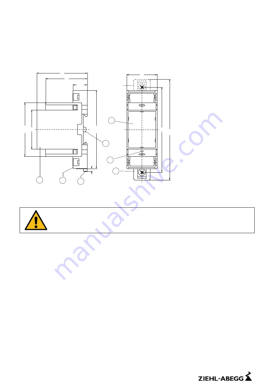
Dimensions - Design V2
Dimensions in mm
1) Top piece
2) Bottom piece
3) Mounting bar
4) Seal mounting link
5) Front plate element
6) Marking for bottom
7) Extensible
bolt
for
wall
fastening with screws. Bolt
bore Ø 4.2 mm
15
Safety instructions and references for putting into operation
Attention!
Safety Instructions and references
please read carefully!
15.1 Explosive atmospheres
•
The increased danger within explosive atmospheres (gas or dust) requires the careful attention of the
safety instructions and references for putting into operation. Observe the national safety rules and
regulations for prevention of accidents as well as the standard EN 60079-14 / VDE 0165-1. All work
for the connection, for putting into operation and maintenance is to be implemented by qualified,
responsible technical personnel. Inappropriate behaviour can cause heavy personal damage and
damages to property.
•
The response of the device must directly switch off the motor, also when used together with
inverters. This must be implemented with circuitry.
15.2 Special remarks for explosive gas atmospheres areas (Zone 0, 1 and 2)
•
The device must be installed outside potentially explosive gas atmospheres unless the device is
protected by a suitable ignition protection type (for example a flameproof enclosure).
15.3 Special remarks for use in the presence of combustible dust (Zone 20, 21 and 22)
•
The device must be installed outside potentially explosive dust atmospheres unless the device is
protected by a suitable enclosure for dust atmospheres.
48
58
4
5
3
6
1
,8
16,5
(9
0
)
Option
9
8
1
1
6
35
3
4
1
2
5
7
6
Содержание U-EK230E
Страница 11: ...21 EU Declaration of conformity ...
Страница 12: ...22 UKCA Declaration of Conformity ...


