background image

Reorient or relocate the receiving antenna.

Increase the separation between the equipment and receiver.

Connect the equipment into an outlet on a circuit different from that to which the receiver is 
connected.

Consult the dealer or an experienced radio/TV technician for help 

Labeling Requirements

The Original Equipment Manufacturer (OEM) must ensure that FCC labelling requirements are met. 
This includes a clearly visible label on the outside of the OEM enclosure specifying the appropriate 
Panasonic FCC identi

er for this product as well as the FCC Notice above. The FCC identi

er is FCC 

ID: T7V1740. This FCC identi

er is valid for all PAN1740 modules.

In any case the end product must be labelled exterior with "Contains FCC ID: T7V1740"

Antenna Warning

For the related part number of PAN1740.
This device is tested with a standard SMA connector and with the antennas listed below. When 
integrated in the OEMs product, these 

xed antennas require installation preventing end-users from 

replacing them with non-approved antennas. Any antenna not in the following table must be tested to 
comply with FCC Section 15.203 for unique antenna connectors and Section 15.247 for emissions.

Item

Part Number

Manufacturer

Frequency Band

Type

Gain (dBi)

1

LDA212G3110K

Murata 

2.4 GHz 

Chip-Antenna 

+0.9 

RF Exposure

The radiated output power of PAN1740 with mounted ceramic antenna (FCC ID: T7V1740) is far 
below the FCC radio frequency exposure limits.
Nevertheless, the PAN1740 shall be used in such a manner that the potential for human contact 
during normal operation is minimized

1.7.3

Industry Canada Certi

cation @ AM-MODBUS-WB, AM-STICK-WB

This device contains "Contains IC: 216Q-1740".
PAN1740 is licensed to meet the regulatory requirements of Industry Canada (IC), license: IC: 216Q-
1740.
Manufacturers of mobile, 

xed or portable devices incorporating this module are advised to clarify any 

regulatory questions and ensure compliance for SAR and/or RF exposure limits. Users can obtain 
Canadian information on RF exposure and compliance from www.ic.gc.ca.
This device has been designed to operate with the antennas listed in the Table above, having a 
maximum gain of 0.9 dBi. Antennas not included in this list or having a gain greater than 0.9 dBi are 
strictly prohibited for use with this device. The required antenna impedance is 50 ohms. The antenna 
used for this transmitter must not be co-located or operating in conjunction with any other antenna or 
transmitter.
Due to the model size the IC identi

er is displayed in the installation instruction only and can not be 

displayed on the modules label due to the limited size (8.7x15.6mm).

IC Notice

The devices contains "Contains

 IC: 216Q-1740

", including the antennas, which are listed in above, 

complies with Canada RSS-GEN Rules. The device meets the requirements for modular transmitter 
approval as detailed in RSS-GEN. 

Operation is subject to the following two conditions: 

1. This device may not cause harmful interference
2. This device must accept any interference received, including interference that may cause unde-

sired operation

Le présent appareil est conforme aux CNR d'Industrie Canada applicables aux appareils radio 
exempts de licence.

L'exploitation est autorisée aux deux conditions suivantes : 

1. l'appareil ne doit pas produire de brouillage, et
2. l'utilisateur de l'appareil doit accepter tout brouillage radioélectrique subi, même si le brouillage 

est susceptible d'en compromettre le fonctionnement.

Assembly instructions 

ECblue BASIC-MODBUS, ECblue BASIC

General notes

L-BAL-F079D-GB 2044 Index 002

Part.-No. 

8/80

Содержание ECblue

Страница 1: ...ue BASIC MODBUS ECblue BASIC Motor sizes D 116 G 152 EC fans and motors with and highest ef ciency for livestock houses Assembly instructions Keep for reference L BAL F079D GB 2044 Index 002 Part No english ...

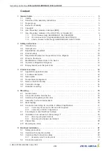
Страница 2: ...ional description 12 3 3 Name plate 12 3 4 Temperature management 14 3 5 Note on the ErP directive 14 3 6 Transport storage 14 3 7 Disposal recycling 14 4 Mounting 15 4 1 General notes 15 4 2 Connection lead terminal box 15 4 3 Version with separate junction box 16 4 4 Assembly in a humid atmosphere 16 4 5 Motorheating 16 4 6 Connection according UL and CSA in different applications 17 4 6 1 Conne...

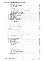
Страница 3: ...ions 37 5 17 Accesories main swithc Zenec 37 5 18 add on modules for ECblue BASIC 38 6 Start up 39 6 1 Prerequisites for commissioning 39 7 Communication options for programming 40 8 Bluetooth communication module AM STICK WB 41 8 1 Bluetooth communication module AM STICK WB option 41 8 2 Function 41 8 3 Label Datamatrix Code serial number 42 8 4 Establishing the Bluetooth connection 43 9 Hand hel...

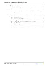
Страница 4: ... 70 12 2 1 UL Ratings 70 12 2 2 UL Overload protection 71 12 2 3 UL Short Circuit Current Rating 72 12 3 Connection diagrams 73 12 4 Application examples 75 12 4 1 Installation with ventilation computer CTE AH L and main switch Zenec 75 12 4 2 Overvoltage protection 76 12 5 EC Declaration of Incorporation 77 12 6 Index 79 12 7 Manufacturer reference 80 12 8 Service information 80 Assembly instruct...

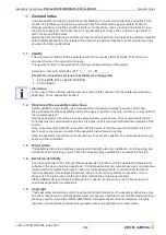
Страница 5: ...tain safety instruc tions that must be complied with as well as information that is required for failure free operation of the device Keep these assembly instructions together with the device It must be ensured that all persons that are to work on the device can refer to the assembly instructions at any time Keep the assembly instructions for continued use They must be passed on to all successive ...

Страница 6: ...erefore not taken into consideration in translations 1 7 1 FCC IC Statements AM MODBUS W AM PREMIUM W In case that the AM MODBUS W module or the AM PREMIUM W module is installed in the ECblue the following applies FCC Compliance US This device complies with Part 15 of the FCC Rules Operation is subject to the following two conditions 1 this device may not cause harmful interference and 2 this devi...

Страница 7: ...ntennas which are listed below complies with Part 15 of the FCC Rules The device meets the requirements for modular transmitter approval as detailed in FCC public Notice DA00 1407 transmitter Operation is subject to the following two conditions 1 this device may not cause harmful interference 2 this device must accept any interference received including interference that may cause unde sired opera...

Страница 8: ...0 is licensed to meet the regulatory requirements of Industry Canada IC license IC 216Q 1740 Manufacturers of mobile fixed or portable devices incorporating this module are advised to clarify any regulatory questions and ensure compliance for SAR and or RF exposure limits Users can obtain Canadian information on RF exposure and compliance from www ic gc ca This device has been designed to operate w...

Страница 9: ...mplies Ces obligations incluent une étiquette clairement visible à l extérieur de l embal lage externe comportant l identifiant IC du module Panasonic inclus ainsi que la notification ci dessus Les identifiants IC sont IC 216Q 1740 Ces identifiants sont valides pour tous les modules PAN1740 Dans tous les cas les produits finaux doivent indiquer sur leur emballage externe une des mentions suivantes Cont...

Страница 10: ...red to be reliable The device and its accessories must only be used in a flawless condition and installed and operated in compliance with the assembly instructions and or operating instructions Operating out side the device s technical specifications see name plate and attachment technical data can lead to a defect in the device and additional damage Information A separate fault and performance moni...

Страница 11: ...d personnel Waiting period at least 3 minutes Through use of capacitors danger of death exists even after switching off the device through directly touching the energized parts or due to parts that have become energized due to faults The controller housing may only be removed or opened when the power line has been switched off and a period of three minutes has elapsed since switching it off Attent...

Страница 12: ...n line with their intended use The supplied and certified guard grille of ZIEHL ABEGG SE fans is designed in accordance with DIN EN ISO 13857 Table 4 from the age of 14 up In the event of deviations further structural protective measures must be taken for safe operation Any use below 10 C is dependent on not being subjected to unusual sudden or mechanical loads or stresses on the material see minim...

Страница 13: ...manufacture 18 Protection rating Max ambient temperature authorisation at rated power 6 Partnumber ZIEHL ABEGG SE 19 Current output in case of short circuit 7 Series number 20 Indication of more detailed information in the assembly instructions 8 Rated voltage Rated frequency Power Rated current 9 Rated speed max ambient temperature Protection rating Temperature class Efficiency class 10 Product na...

Страница 14: ...ee rating plate and the permissible carrying loads of the means of transport Wear safety clothing shoes and cut resistant safety gloves when handling Transport the fan s either in the original packaging or in the case of larger fans on the dedicated transportation fixtures Holes drilled in support arms wall ring plates and motor block Do not transport the fan by the connecting cable Avoid shocks an...

Страница 15: ...o EN 60335 If the mounting height danger area above the reference plane is greater than or equal to 2700 mm and is not reduced by auxiliary means such as chairs ladders working platforms or floor space on vehicles a guard grille is not necessary on the fan If the fan is located in danger zone then the manufacturer or operator shall ensure that hazards shall be prevented by appropriare protective co...

Страница 16: ...h at 80 100 of maximum speed to remove any moisture that has penetrated inside 4 5 Motorheating A continuous power supply is required for safe operation down to the minimum permitted ambient temperature see technical data If the motor is not operated with an existing power supply no setting signal switch off by enable the motor heating switches back on automatically at a controller inside temperat...

Страница 17: ...ealing the conduit connections make sure the supplied O rings are used When screwing the conduits into the thread adapters use UL approved sealing tape e g Teflon tape The opposite end of the installation tube to the motor must be sealed so that moisture and dust cannot be sucked in by the slight vacuum pressure existing in the terminal compartment The locking screws used within the MK116 and MK152...

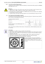
Страница 18: ...2 70 friction coefcient µges 0 12 7 Nm 17 Nm 33 Nm Screw penetration 1 5 x d 1 5 x d 1 5 x d When using screws with different friction values or strength classes different tightening torques may be necessary Information Pay attention to a sufficient screw in length in the motor flange Excess screw length not permissible and it may result in the rotor being brushed against or blocked Every screwing c...

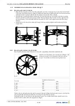
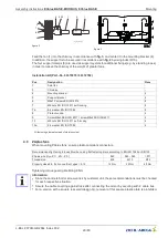
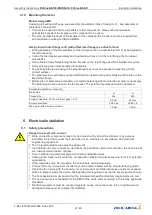
Страница 19: ...all and tighten with cable tie 5 to fan support arm 4 8 2 Mounting with stainless steel brackets Mounting the stainless steel brackets is done with a separately obtainable installation kit figure 1 Mark the mounting bracket 4 in accordance with fig 1 in the chimney 3 using a 4 x 90 template drill hole center dis tance a in accordance with the mounting bracket 4 Fan size Adjustable diameter area min ...

Страница 20: ... EN ISO 10 511 self locking 4 10a 8 4 washer EN ISO 7089 4 All fastening elements made of stainless steel 4 9 ZAplus fans When mounting ZAplus fans ensure plastic compliant connectors Recommended tightening torques MA when using flat fastening discs according to EN ISO 7089 or DIN125 ZAplus size tye ZC ZN ZF 040 045 063 071 Thread size M8 M10 M12 Property class 8 8 friction coefcient µges 0 12 12 N...

Страница 21: ...n coefcient µges 0 12 9 5 Nm 23 Nm Screw penetration 0 83 x d 0 83 x d Max permissible screw overhang 1 0 mm 1 5 mm 5 Electrical installation 5 1 Safety precautions Danger due to electric current Work on electric components may only be carried out by trained electricians or by persons instructed in electricity under the supervision of an electrician in accordance with electrical engineering regula...

Страница 22: ...blue BASIC connection version example 1 ECblue for line and relay hose cable 5 x 1 5 mm2 LiF9Y11Y JB BN BU GNYE WH WH brown L1 Voltage supply blue N green yellow PE white 11 Relay white 14 K1 3 ECblue for line and relay hose cable 6 x 1 5 mm2 LiF9Y11Y JB BK GNYE WH WH BN BU or GY brown L1 Voltage supply blue or grey L2 black L3 green yellow PE white 11 Relay white 14 K1 1 and 3 ECblue for control ...

Страница 23: ...condition at delivery Remove plastic fastener if necessary and insert enclosed cable glands entry points that are not used must remain sealed 3 Insert and connect lines correctly note the respective connection diagram 4 Attach cover of controller housing again carefully in correct position before start up Attention The seal of the end cap can adopt the contour of the stator bushing in time Therefo...

Страница 24: ...nductor cross section rigid min 0 2 mm2 0 2 mm2 0 2 mm2 Conductor cross section rigid max 10 mm2 1 5 mm2 1 5 mm2 Conductor cross section flexible min 0 2 mm2 0 25 mm2 0 2 mm2 Conductor cross section flexible max 6 mm2 1 5 mm2 1 5 mm2 Conductor cross section flexible with wire end ferrule without plastic sleeve min 0 25 mm2 0 25 mm2 0 25 mm2 Conductor cross section flexible with wire end ferrule withou...

Страница 25: ...hten the collar to the specified torque with a suitable torque wrench Insert the cable through the cable gland into the housing Fit the union nut by hand and tighten slightly Tighten the union nut to the specified torque of the cable gland using the torque wrench To insert two cables through one cable gland use a seal insert with 2 boreholes The seal insert supplied can only be used for a limited ra...

Страница 26: ...ination grease dust or other impurities Use of a damaged cable is not allowed Two lines may only be fed through one cable gland with a sealing insert for two lines When using the seal insert for two cables it is not permissible to use the corresponding cable gland with only one cable Only use cables with a cylindrical cross section For other cross sections e g ribbon cables special seal inserts ar...

Страница 27: ...integration into different networks X With AM MODBUS auxiliary module possible 5 5 EMC compatible installation 5 5 1 Harmonics current for 3 types According to EN 61000 3 2 these devices are to be classified as professional devices Connection to a low voltage supply public networks is allowed insofar as this has been clarified with the respective energy supply company responsible 5 5 2 Control cable...

Страница 28: ...d cable the type of routing the operating conditions and according to the standards applicable on site The specification for the maximum admissible line fuse of the device must be observed see technical data Possible components for the line protection recommendation Safety fuses of operating class gG whole range fuse cartridges for general applications according to EN 60269 1 Line protection switch...

Страница 29: ...e mains connection and the PE conductor and they are therefore suitable for use in a Grounded Delta System 5 7 Systems with residual current protective devices Whether the use of a residual current protective device RCD is necessary or allowed depends on the design of the low voltage system on which the device is to be operated The assessment whether or which residual current protective device sho...

Страница 30: ...on 10V GND E1 10 kΩ Speed setting by 10 kΩ potentiometer at terminals 10 V and GND pick off at terminals E1 10V GND E1 24V PWM f 1 10 kHz 10 kΩ 10 V GND E1 24 V E1 E1 GND 15 28 V Control via external setting signal PWM CTE AH X L GND E1 PWM A4 24V Connection to ZIEHL ABEGG ventilation computer with PWM output 5 10 Output voltage 10 V Voltage supply e g for speed setting by external potentiometer P...

Страница 31: ...An external fault indicator is available over the potential free contact of the built in relay max contact rating see Technical data and connection diagram The relay is energised during operation I e on the ECblue BASIC MODBUS contacts 11 14 are bridged and on the ECblue BASIC contacts 13 14 In case of failure the relay is de energised see Diagnostics Faults Changeover contact for ECblue BASIC MOD...

Страница 32: ... interface e g lightning Except the data link A D B D and GND for automatic addressing additional ID1 ID2 see following chapter no further cable cores of the data line may be used Pay attention to sufficient distance from powerlines and motor wires min 20 cm A maximum of 64 participants can be directly connected to one another and a further 63 participants via a repeater The precise number depends ...

Страница 33: ...ncorrect When using telephone cable with four cable cores we recommend the following allocation A D red B D black ID1 ID2 yellow for automatic addressing GND white Default interface parameter Baudrate 19200 Bits 8 Parity Even Stop bits 1 Handshake none Information Addressing is performed depending on version by display an external terminal or a PC with the appropriate software automatic addressing...

Страница 34: ... the repeater of the Z G 1NE type can be used only it can relay the addressing signal Maximum number of members in automatic addressing With hand held terminal type A G 247 and control unit NETcon type A G 102ANE max 63 members With control module UNIcon MODBUS master type CXE AV E and CXG 24AV E a max 32 participants With control module UNIcon MODBUS master type CXG 327AN E R a max 62 participant...

Страница 35: ...g signal E1 Min Internal offset for analog input E1 Si Rotational speed specification signal depending on connection version 0 10 V 4 20 mA 0 100 PWM 0 100 MODBUS If the internal setting E1 min factory setting 5 is exceeded the system starts the motor with a factory set minimum speed depending on the motor type typically 9 of the rated speed see rating plate If the specification signal has exceeded ...

Страница 36: ...Si Rotational speed specification signal depending on connection version 0 10 V 4 20 mA 0 100 PWM 0 100 MODBUS Relations The torque is set proportionally do the square of the specification signal M Si2 It is important to consider that a minimum torque of 12 must be added to improve the start up behaviour Torque specification 100 x Si 10 V x 0 94 2 0 12 Si in V This means that on fans with a quadratic...

Страница 37: ...an be made if required fit a bridge between the GND terminal and the PE connection terminal for shield 5 17 Accesories main swithc Zenec Main switch for ECblue fans with 100 function Type Zenec Part No 349068 Housing protection class IP65 0 Switches off the fan lockable Auto Controlmode 100 Fan runs independent of the preset signal at full speed 100 function You can find further details in the opera...

Страница 38: ... app AM PREMIUM AM PREMIUM W 349092 349051 Universal control module By plugging on the AM PREMIUM module the device becomes a universal controller sensors can be connected directly The device can be communicated with using the hand held terminal type A G 247NW Connection by cable via the MODBUS interface or wirelessly by radio AM MODBUS W AM CAN OPEN 349064 CANOPEN module To integrate the device i...

Страница 39: ...ely closed according to the suitable installation position 6 Connection data complies with the specifications on the rating plate During start up check the following 1 Check the direction of rotation see rotation direction arrow on the fan blade impeller base plate or support plates on suction side or rating plate 2 Check for quiet low vibration operation Strong vibrations due to erratic operation ...

Страница 40: ...r the ZAset PC software Information For information on installation creating the connection and operation refer to the separate documentation for the auxiliary module Information on presets are not binding these values can differ depending on the software version and customer specific pre settings Attention Very powerful electrical devices which you may not be able to see can be operated remotely C...

Страница 41: ...S devices from version 11 onwards In a hard wired system wireless communication is primarily designed to provide a second interface for communicating with the device e g for configuration and diagnostics The wireless communica tion uses the MODBUS protocol MODBUS TCP The Bluetooth addressing takes place via the Bluetooth address The Bluetooth scan automatically detects all devices within range The ...

Страница 42: ... position and make sure that clear assignment to the relevant product is possible This enables you to guarantee that even if the rating plate is covered up e g due to the installation situation easy commissioning and service via Bluetooth are possible There is also a QR code on the sticker which is used to download the ZAset Mobile app The serial number to link to the AM STICK WB can be entered ma...

Страница 43: ...the Settings area with the gear wheel symbol 3 Switch on the line voltage to the fan frequency converter in compliance with the safety instruc tions 4 Activate the Bluetooth connection on the mobile device smartphone Additionally allow location determination in Android Assembly instructions ECblue BASIC MODBUS ECblue BASIC Bluetooth communication module AM STICK WB L BAL F079D GB 2044 Index 002 Pa...

Страница 44: ...if necessary 6 ZAset then starts searching for devices in range and adds compatible devices to a list 7 Briefly tap the desired device in the list to select it ZAset Mobile then immediately establishes a data connection with this device Assembly instructions ECblue BASIC MODBUS ECblue BASIC Bluetooth communication module AM STICK WB L BAL F079D GB 2044 Index 002 Part No 44 80 ...

Страница 45: ...pens to link with the serial number If a binding already exists you have to enter the PIN see second stage The serial number can either be entered manually by reading it off and entering it in a text field or by scanning the data matrix code see additional adhesive label Second stage Access code PIN Enter the PIN 9999 factory setting and confirm with OK Assembly instructions ECblue BASIC MODBUS ECbl...

Страница 46: ...unauthorised access 9 If required enter a name of your choice alias Example 01_ECblue Assembly instructions ECblue BASIC MODBUS ECblue BASIC Bluetooth communication module AM STICK WB L BAL F079D GB 2044 Index 002 Part No 46 80 ...

Страница 47: ...lour of the Bluetooth symbol changes from red to green 11 Actual values on Dashboard when connection is established successfully Assembly instructions ECblue BASIC MODBUS ECblue BASIC Bluetooth communication module AM STICK WB L BAL F079D GB 2044 Index 002 Part No 47 80 ...

Страница 48: ...ntification etc 4 Error history 5 Parameter 6 back to Dashboard 7 Analysis 8 Speed control by variable Information Please observe the additional information in the app documentation and the operating instructions download for the AM STICK WB Assembly instructions ECblue BASIC MODBUS ECblue BASIC Bluetooth communication module AM STICK WB L BAL F079D GB 2044 Index 002 Part No 48 80 ...

Страница 49: ...ion in which operation at full speed is possible in case of failure of the setting signal It is selected by activating the setting Set Intern 2 factory setting 100 via the digital input When using the 100 function changes to the Set Intern 2 and Max Speed parameters are not allowed Setting Set Internal1 Setting only in Controlmode 4 active see Controller Setup Via the inputs D1 E1 it is possible t...

Страница 50: ... can be protected against unintentional changes by a pin code With further pin codes putting back to pre setting is possible PIN 0010 Release of the service settings with programmed PIN Accesslevel 0 see Controller Setup Menu groups Service Controller Setup IO Setup Motor Setup PIN 1234 Freischalten Menu group Setting Release of the menu group for the user setting with programmed PIN Accesslevel 0...

Страница 51: ...in the terminal with the P key 9 3 Menu group Info Info Speed Motor speed Motor current Display of internal motor current metering precision approx 10 Brake control Display of modulation 0 100 metering precision approx 10 Motor input power Display of input power metering precision approx 10 Assembly instructions ECblue BASIC MODBUS ECblue BASIC Hand held terminal A G 247NW L BAL F079D GB 2044 Inde...

Страница 52: ...rnal3 via digital input possible see IO Setup 5 Fixed speed Default Internal2 without switching possibility to other default 6 Fixed speed Default Internal3 without switching possibility to other default 7 Control by E1 quadratic characteristics 8 Control by E1 custom characteristics 9 Control by E1 air flow control 10 Speed control register h2 fractional air flow control 11 Speed control register h...

Страница 53: ...IN Accesslevel The PIN Accesslevel determines for which setting ranges a PIN must be entered Setting Function 2 Factory setting All menu groups are visible settings are possible without a PIN 1 The menu group Setting is free i e changes are possible without a PIN PIN 0010 for changes in the menu groups Controller Setup IO Setup and Motor Setup these menu groups are not visible without a PIN 0 All ...

Страница 54: ... of ON required for 100 function If the analogue input E1 is not required for specifying the fan speed this can be used as a digital input see E1 function The same functions can be assigned for E1 as for D1 Attention Never apply line voltage to the digital input Function Designation 5D Set Internal2 factory setting for 100 Function Fixed speed Default Internal2 active Function with selected contro...

Страница 55: ... is active at the digital input when the contact is open in factory setting D1 E1 Inverting OFF so that the maximum fan speed is still possible even when the line to the digital input is interrupted Attention This function is implemented by switching to Set Intern3 A setting of 100 rated speed of Set Intern3 is a prerequisite for operation at maximum speed The device and its internal components ar...

Страница 56: ...ice receives no message in the time window a definable function is executed Watchdog time in seconds Setting range 0 255 sec Factory setting 0 sec off Watchdog Mode Watchdog Mode 0 No function default OFF from FW 13 1 Fault K1 function h15 in case of communication fault WDT 2 Constant speed 1 in case of communication fault WDT 3 Fault constant speed 1 in case of communication fault WDT 4 Fault by E...

Страница 57: ...ry setting 19200 UART Mode Setting transfer format Valid values 8N1 8O1 8E1 8N2 Factory setting 8E1 9 6 Menu group Motor Setup Motor Setup Rated speed MotorRatedCurr The following controller presettings are dependent on the respective motor design and are only shown for information Rated speed MotorRatedCurr Rotat Direction Value motorheating Rampup time Rampdown time Rotat Direction Value motorhe...

Страница 58: ...Suppression2 Range2 min Range2 max Suppression3 Range3 max Range3 max Assembly instructions ECblue BASIC MODBUS ECblue BASIC Hand held terminal A G 247NW L BAL F079D GB 2044 Index 002 Part No 58 80 ...

Страница 59: ...00 3 4 1 2 09 05 2007 v_hochlaufzeit_ruecklaufzeit vsd 1 external Signal 2 Setting 3 Rampup time 4 Rampdown time 9 6 2 Suppression of speeds Suppression of up to three speed ranges Under certain circumstances it is possible to prevent disturbing noises that can arise at certain speeds due to resonances Example for suppression of 2 ranges Idealized principle diagram A D P 50 50 R 0 I S 100 I 35 max...

Страница 60: ...e device Diagnostic IGBT temp Display of the internal temperature of the power semiconductor Inside Temp Display of electronics internal temperature MCU Temp Display of the internal temperature of the microcontroller E1 Input no function DC Voltage DC link voltage constant approx 400 V Line voltage Stateflags Faultflags PIN Accesslevel Momentarily adjusted PIN Accesslevel Controller Setup Assembly i...

Страница 61: ...the memory Example line fault Position 1 latest event The last 10 1 10 events are saved The desired position can be selected with the keys 19 number of all previous faults An error message appears alternately with the actual value display Diagnostic faults Assembly instructions ECblue BASIC MODBUS ECblue BASIC Hand held terminal A G 247NW L BAL F079D GB 2044 Index 002 Part No 61 80 ...

Страница 62: ...hes When indicated clear foreign bodies dirt from the fan Active temperature management effective Motor or electronics overheated Check for free air passages remove foreign bodies if necessary see Impeller blocked or dirty Check temperature of supply air Check installation space air speed over heat sink Air flow to low Fan turns too slowly see Fan turns too slowly Airways blocked Check for free air...

Страница 63: ...e or mains phase the unit switches off after a delay approx 200 ms Only functioning with an adequate load for the controller Following a shutoff a startup attempt is made after approximately 15 seconds if the voltage supply is high enough This keeps occurring until all 3 supply phases are available again Check power supply 5 x 0 Motor blocked If after 8 seconds of commutation no speed is measured ...

Страница 64: ... stay below the specified limit for more than 75 seconds the device will switch off with an error message 13 x 0 Line voltage too high Cause to high input voltage If the line voltage increases above a specified limit the motor will switch off If the line voltage drops below the specified limit within 75 seconds then the controller will attempt to start Should the line voltage stay above the specified ...

Страница 65: ...irection at a setting signal above 0 To protect the electronics against too high braking current this function is partly fan dependent only possible up to a certain speed value The braking function also becomes active to bring the fan to a standstill when this is driven with a speed below 100 min 1 without control At speeds above 100 min 1 the motor control does not intervene When driven in correc...

Страница 66: ...y impellers corroded in this way must be replaced immediately Deposits on the motor particularly on the cooling vanes and in recesses on the rotor can lead to reduced cooling performance and the motor switching off prematurely For this reason remove deposits quickly see chapter Cleaning Maintenance interval in accordance with the degree of contamination of the impeller Check the fan at regular int...

Страница 67: ...le corresponding to the installation position must be checked for free passage In case of improper cleaning work no warranty is assumed regarding corrosion formation paint adhesion for unpainted painted fans To avoid accumulation of moisture in the motor the fan must be operated for at least 1 hour at 80 to 100 of the maximum speed before the cleaning process After the cleaning process the fan mus...

Страница 68: ...um ambient temperature valid for the respective fan Operation below 25 C as well as partial load operation for refrigeration applications is only possible with special bearings for refrigeration applications on request If special bearings for refrigeration applications are installed in the fan please observe the permissible maximum temperatures in the technical documentation of the product To avoi...

Страница 69: ...rmonic current in accordance with EN 61000 3 2 are guaranteed For 3 types According to EN 61000 3 2 see Assembly instructions Electrical installation EMC compatible installation Harmonics current for 3 types Contact rating of the internal relay AC 250 V 2 A Max leakage current according to the defined networks of EN 60990 3 5 mA dB A values see product catalog Protection class of motor according to...

Страница 70: ...30 W 16 kHz 7 4 A 218 Vac rms 70 MK 116 I 07 H MK 116 I 11 H MK 116 I H A16 MK116 0011 MK116 0019 3x 200 480 Vac 1300 2500W 4 0 3 2A 2400 W 16kHz 4 7 A 460Vac rms 40 3x 200 480 Vac 1180 2500W 3 2 3 6A 2350 W 16kHz 4 4 A 460Vac rms 60 3x 200 480 Vac 820 1880W 2 4A 1780 W 16kHz 2 3 A 460Vac rms 70 MK 116 I 07 I MK 116 I 11 I MK 116 I H A19 MK116 0012 MK116 0021 1x 100 130 Vac 630 W 4 9A 580 W 16kHz ...

Страница 71: ... 0016 3x 200 480 Vac 3000 4100W 9 7 5 5A 2850 3900 W 16kHz 10 3 5 8 A 180 440Vac rms 50 3x 200 480 Vac 2600 4100W 8 6 5 6A 2470 3900 W 16kHz 9 5 8 A 180 440Vac rms 60 3x 200 480 Vac 1600 3000 W 6 0 4 7A 1500 2850 W 16kHz 5 5 4 3 A 180 440Vac rms 70 Placeholder see ZIEHL ABEGG Nomenclature Power data of the motor in the fan standing nearby the above data on the rating plate 12 2 2 UL Overload prote...

Страница 72: ...rraz Shawmut TRS10R MK116 I I RK5 240 V 25 A 250 V e g Ferraz Shawmut TR25R MK116 I B MK116 I G MK152 I E RK5 240 V 50 A 250 V e g Ferraz Shawmut TR50R MK152 I B RK5 480 V 15 A 600 V e g Ferraz Shawmut TR15R MK116 I A MK116 I F MK116 I H MK152 I D RK5 480 V 30 A 600 V e g Ferraz Shawmut TR30R MK152 I A MK152 I H RK5 480 V 25 A 600 V e g Ferraz Shawmut TR30R MK152 I F MK152 I G Integrated solid sta...

Страница 73: ... 485 PORT 1 PORT 2 Eingang Input 0 10 V 0 100 PWM 10 0 V 100 0 PWM 4 20 mA 4 0 100 1 Auto 0 100 3 01 1 Line voltage see rating plate 2 Relay output K1 for fault reporting factory function max contact load AC 250 V 2 A During operation the relay is energised i e the connections 11 and 14 are bridged In case of a fault the relay is de energised i e the connections 11 and 12 are bridged 3 0 contact o...

Страница 74: ...output K1 for fault reporting factory function max contact load AC 250 V 2 A During operation the relay is energised i e the connections 13 and 14 are bridged In case of a fault the relay is de energised 3 Slot for AM add on module 4 0 contact open full fan speed 100 1 contact closed automatic speed control by setting signal 0 100 5 Input 0 10 V 4 20 mA 0 100 PWM Information In versions with conne...

Страница 75: ...ECblue 5 Cable for line and relay at ECblue 6 conductor 5 not connected Danger due to electric current Make absolutely sure that the mains voltage and the control are a sufficient distance apart Assignment 7 x 1 5 mm2 Terminals No Zenec GNYE PE PE 1 N 6 2 L1 2 3 4 full speed automatic speed control 9 10 5 6 if in Zenec position 0 no failure report is to take place 7 8 Assignment 5 x 1 5 mm2 Termina...

Страница 76: ... run between different buildings an effective excessive voltage protection is to be installed onsite on the first device in the respective building Generally all surge arrestors work in such a way that they conduct the induced energy via the potential equalization to the foundation ground electrode Due to the high currents that can occur here it is necessary to keep the conductor lengths as short a...

Страница 77: ...chinery electrical equipment of machines Part 1 General requirements EN ISO 12100 2010 Safety of machinery General principles for design Risk assessment and risk reduction EN ISO 13857 2008 Safety of machinery safety distances to prevent danger zones being reached by the upper limbs Note The maintenance of the EN ISO 13857 2008 relates only to the installed accidental contact protection provided t...

Страница 78: ...ions of the EC Machinery Directive Künzelsau 28 10 2020 location date of issue ZIEHL ABEGG SE Dr W Angelis Head of Technics Ventilation Technology name function ZIEHL ABEGG SE Dr D Kappel Head of Electrical Systems name function signature signature Assembly instructions ECblue BASIC MODBUS ECblue BASIC Enclosure L BAL F079D GB 2044 Index 002 Part No 78 80 ...

Страница 79: ...le atmosphere 12 Imbalance 54 Input resistance 59 interface parameter 31 iPad 36 iPhone 36 IT System 27 L leakage current 60 lifting beam 14 line fuse 60 line protection 26 M MODBUS 30 MODBUS Recovery 57 N NFPA79 23 O one quadrant drives 12 P PFC 28 pin code 44 PIN input 44 power electronics 28 R Rampdown time 51 Rampup time 51 rating plate 58 RCD 27 relay 29 Relay output 29 residual current prote...

Страница 80: ...g de http www ziehl abegg com 12 8 Service information If you have any technical questions while commissioning or regarding malfunctions please contact our technical support for control systems ventilation technology phone 49 0 7940 16 800 Email fan controls service ziehl abegg de Our worldwide contacts are available in our subsidiaries for deliveries outside of Germany see www ziehl abegg com Ass...

Отзывы: