


ThroTTle algorIThMs
The MC1000C supports a range of different throttle algorithms to suit different applications and
motor types. These can be configured over CAN bus, with an EVMS Monitor, or pre-configured
from the factory by request. Adjustable parameters are ramp rate, speed control type and torque
control type.
Ramp rate is represented as a value of 0-4, being the rate of change of the throttle output, where 0
is fastest (near instant response) and 4 is slowest (several seconds to ramp up to full throttle). The
default value of 1 is suitable for most applications.
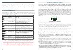
Speed Control and Torque Control can be
individually set to either Linear, Semiquadratic,
Quadratic or Off. The response curves for
each are shown in the graph to the right.
Linear control gives an output proportional to
input. Semiquadratic and Quadratic control
are typically used where gentler low throttle
response is desired. If both Speed Control and
Torque Control are enabled, the output is limited
to whichever is lower at any time. If one of the
two is set to Off, it is effectively unrestricted/
uncontrolled, so only the other parameter has an
effect. If both Speed and Torque Control are Off,
the controller’s output will be disabled.
The default setting of Linear for both speed and torque is suitable for most series DC motors, giving
a familiar driving experience. For permanent magnet motors, usually semiquadratic torque control
works well, with speed control either Off or in Linear mode. Speed only control is not normally
suited to traction applications (cars/bikes) but can be useful for aircraft or boats.
operaTIon
TIps for besT perforManCe
Many drivers are accustomed to keeping revs low in their petrol vehicles in order to maximise
efficiency, since petrol engines are very inefficient at high revs. Well, electric drive systems are the
other way around! The single most effective way to maximise performance from your motor and
controller is to keep your motor revs high – around 3000-4000rpm with most Series DC motors.
For a given power output, driving a motor at higher speed uses more voltage but less current,
which reduces copper losses in the motor and resistive heating in the controller. Dropping down
a gear reduces motor amps by about 30%, which can actually halve the heat generated in your
controller – and hence double the continuous power capability. (Caution: Most Series DC motors
are rated to 5000rpm max so be careful not to exceed this speed.)
TherMal proTeCTIon
If your controller heatsink temperature reaches about 70˚C (150˚F), the controller will commence
thermal cutback, smoothly reducing power to mitigate further heating. The status LED will flash
green/red while in this state. If the controller temperature reaches about 90˚C (200˚F), the controller
will shut down completely to avoid overheating which could damage components.
The controller’s power rating depends somewhat on airflow to cool the housing. If you are
experiencing thermal cutbacks, it may be useful to add fans or ducts to increase airflow. Driving
more slowly and keeping motor revs high will also help keep the motor controller cooler. If
thermal problems persist, it may be useful to add an external water cooling system or external
heatsink, which can be mated to the flat aluminium base of the controller (with thermal paste in
between).
12v logIC supply
The MC1000C has an internal regulated power supply on its 12V input which allows it to operate
safely and correctly over an input voltage range of 8-18VDC. As a safety precaution, the controller
will shut down if it detects the control voltage input dip below 8V.
In most installations this will never happen, but if your 12V battery and/or DC/DC converter is very
weak, the voltage may dip when loads such as headlights are turned on, which can trip out the
motor controller. This should be rectified by by fitting a stronger battery and/or DC/DC converter.
MoTor IdlIng funCTIonalITy
The MC1000C includes a basic motor idle functionality, based on a low target speed with low
torque limit. It does not use an RPM sensor for speed feedback, so the speed may vary depending on
load. However it is a simple and effective solution for EV conversions with automatic transmissions
which require the motor to keep turning to maintain oil circulation in the gearbox, or for vehicles
using OEM power steering pumps, air-conditioning compressors, alternators, etc.
The idle speed and torque are configured via CAN bus. Voltage effectively controls target motor
speed and current controls the torque it will use to get there. Ideal values will depend on your
motor and vehicle, but a good starting point is 6V idle voltage and 100A idle current.
Caution: Electric motors can suffer damage if they remain stalled with current
flowing for extended periods of time. Idle functionality is NOT recommended for
“direct drive” vehicles, and in the case of vehicles with manual transmissions, be
sure to put the clutch in when coming to a stop.
9
8


