


poWer WIrIng
reMeMber..
The traction circuits in electric vehicles involve very high power levels, with potentially lethal
voltages and currents involved. Always observe proper precautions and safety procedures when
working on electric vehicles. Always wear safety glasses, use insulated tools where possible, and
check for dangerous voltages with a multimeter before undertaking any maintenance!
If you are unsure, always consult with an experienced EV technician before proceeding.
TypICal WIrIng dIagraM
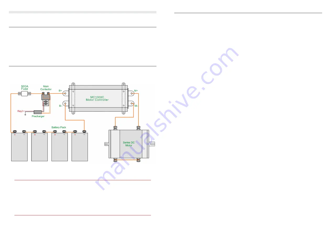
The diagram below shows the basic power wiring. Orange lines represent power cables, which
should be 50sqmm or 1/0 AWG in size, or larger. Control wiring to/from controller not shown.
basic power wiring diagram for MC1000C controller
Caution: Always double check power wiring before turning the system on for the
first time, because reversed polarities or short circuits can do a lot of damage!
When first powering up the completed system, wiring mistakes or faulty throttle
devices could cause unexpected power to the motor, which risks injury or vehicle
runaway. It is highly recommended that the drive wheels be off the ground, and
that nobody is standing in front of or behind the vehicle at the time.
TIps for besT perforManCe
Power cables around 50sqmm or 1/0 AWG in size are recommended for all power wiring
•
between batteries and motor controller, and 50-95sqmm (1/0 to 4/0 AWG) cable between the
motor controller and motor, where average currents are higher. It is best to use double insulated
cable with an orange sheath for compliance with electrical standards.
Ensure all power terminals and connections in your traction circuit are clean and tight. Always
•
use either spring washers or Nyloc nuts to ensure connections will not loosen from vibration
over time. Poor connections have a higher resistance, which can cause them to become hot
when conducting large currents – potentially damaging components.
It is essential to have a precharge device to charge up the motor controller’s internal capacitor
•
bank before closing the main contactor. Closing the main contactor without first precharging
the controller causes a huge current spike which can damage contactors, often welding their
contacts together. A 1KΩ 10W precharge resistor permanently across the main contactor can
work, but is not the safest solution as it does not truly isolate the controller when the key is off.
A better solution is a 2-stage automatic precharger such as our ZEVA Smart Precharger, or an
EVMS with built-in precharger.
Ensure you have an appropriately rated main contactor and fuse protecting your traction circuit.
•
Examples of suitable contactors are the Kilovac EV200 or LEV200, Gigavac GX14, Albright
SW200, or Nanfeng ZJW400A.
For a fuse, a 500A semiconductor type with sufficient DC voltage rating is recommended, such
•
as those from Bussmann, Ferraz-Shawmut, Mersen, Littelfuse, etc. Large fuses tend to be very
slow to blow, typically able to carry twice their rated current for about 1 minute. As such it is
best to use a fuse with a rating slightly above the continuous rating of the motor controller, rather
than one rated for the maximum motor controller current.
The MC1000C motor controller uses aluminium busbars. Aluminium itself is a good conductor
•
of electricity, but unfortunately the (invisible) aluminium oxide which forms on its surface is
a poor conductor. The power terminals are supplied cleaned and with a thin layer of Noalox
contact paste applied to prevent re-oxidation. This paste should be left on the terminals when
are attaching power cables. The force of tightening the bolts will displace the grease and seal the
contact area to prevent corrosion over time.
The power cables in electric vehicles carry a large amount of power, and can emit a lot of
•
electromagnetic interference (EMI) depending on their physical layout. To minimise EMI, it is
best to keep the positive and negative cables close together – both the power cables from battery
pack to controller, and controller to motor. To further reduce EMI, the cables may be twisted
around each other. (For further details on why twisting cables together is helpful for EMI, refer to
http://www.wikipedia.com/wiki/Twisted_Pair)
5
4


