background image

Zeta Alarm Systems  

PC3K 

User’s Manual 

Revision 1.0 

Part # 3000-0002 

Page 24 of 46 

8. Group Configuration 

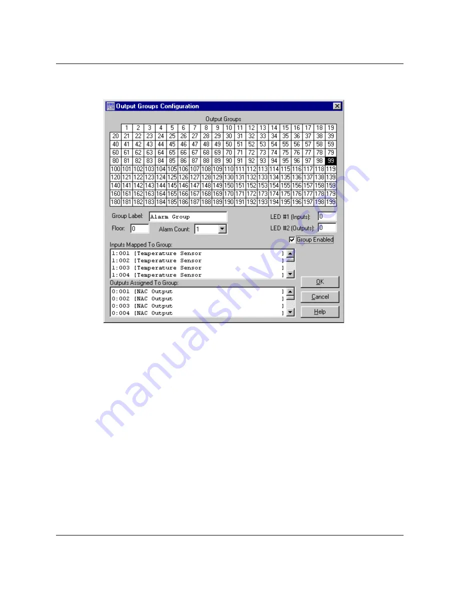
This dialog is used to edit parameters for each output group.  It contains the following areas and controls: 

Group Array 

This array of boxes represents the output groups, where each box is one group. Click on a group to 
display its settings.  Multiple groups may be selected using one of the following methods: 

• 

Hold down the "shift" key and click with the mouse to select a range of groups.  For example, to select 
groups 10 thru 20, click group 10 to select it, then hold down the shift key and click group 20.  This will 
cause groups 10 thru 20 to be highlighted.  (Note: Selecting the groups in the reverse order (20 thru 
10) gives the same result.) 

• 

Hold down the "control" key and click with the mouse to select a group of groups.  For example, to 
select groups 1, 3, 5, and 7, click group 1 to select it, then hold down the control key and click group 3, 
then group 5, then group 7.  This will cause groups 1, 3, 5, and 7 to be highlighted.  (Note: The group 
may be selected in any order.) 

• 

You can select both contiguous and discontiguous ranges using combinations of the shift and control 
key.  For example, to select groups 22, 25, 30 thru 60, and 65, click on group 22, hold down the 
control key, click on groups 25 and 30, then hold down both the control and shift keys, and click on 
group 60, then release the shift key and click group 65. 

Group Parameters 

• 

Group Label - A 20-character courtesy label for the last-selected output group. 

• 

Floor Assignment - What floor the last-selected output group is on; leave "0" if floors are not used. 

• 

Alarm Count - How many inputs must be in alarm before the last-selected output group goes into 
alarm? 

• 

Group Enabled - Use this checkbox to enable or disable the selected output groups. 

Содержание PC3K

Страница 1: ...3K User s Manual Part 3000 0002 Revision 1 0 May 2002 Zeta Alarm Systems Ltd A Division of GLT Exports Ltd 72 78 Morfa Road Swansea SA1 2EN U K http www zeta alarms co uk nrpj zeta alarms fsworld co u...

Страница 2: ...ing Input Configuration ___________________________________________ 18 6 3 System Programming Day Night Schedules ___________________________________________ 19 6 4 System Programming On Off Schedules...

Страница 3: ...____ 40 19 3 1 Listings_______________________________________________________________________________ 40 19 3 2 AC Power_____________________________________________________________________________ 4...

Страница 4: ...eplacement or the refund of the registration fee 1 4 How To Contact Zeta Alarm Systems World Wide Web http www zeta alarms co uk Internet E Mail nrpj zeta alarms fsworld co uk Phone 44 1792 455175 or...

Страница 5: ...system the contents of which are remarkably similar to the contents of this user s manual Why use the online help rather than this manual There are several very good reasons The online help is contex...

Страница 6: ...ogramming Clicking this button will launch the system configuration dialog from which you can set system global properties such as the banner message NAC modes schedules etc Point Configuration Clicki...

Страница 7: ...d to a single class of devices or modules These include SLC Devices Addressable sensors inputs outputs and relays FZA and TZB Devices Networked conventional input zones RLDs Remote LED Drivers RDAs Re...

Страница 8: ...dialog allows you to configure the types and quantities of SLC devices installed on loops 1 8 and A D Move thru the list with mouse clicks tabs or Enters If you attempt to enter a quantity outside the...

Страница 9: ...m Inventory FZAs TZBs This page of the System Inventory dialog allows you to configure the number and addresses of conventional zone input cards installed on the RS 485 network Up to twelve FZAs and T...

Страница 10: ...s provide remote annunciation of system point and group status Each RLD can drive up to 30 LEDs if an RLDX Remote LED Driver Expander is installed it can drive an additional 30 LEDs 60 LEDs total Up t...

Страница 11: ...ntory RDAs This page of the System Inventory dialog allows you to configure the number and addresses of remote LCD displays An RDA Remote Display Annunciator mimics the front panel of the Classic 2000...

Страница 12: ...y CBMs This page of the System Inventory dialog allows you to configure the number and addresses of municipal city box interface modules Up to two CBMs City Box Modules may be installed The first mapp...

Страница 13: ...nventory ZRMs This page of the System Inventory dialog allows you to configure the number of relay modules installed Up to four ZRMs Zone Relay Modules may be installed on the system Each ZRM contains...

Страница 14: ...This page of the System Inventory dialog allows you to configure the number and addresses of DIO modules The DIO Dual Input Dual Output module supplies two Class B inputs and two NAC Relay outputs Up...

Страница 15: ...on Input sensitivities and options Day Night Schedules Day Night schedules and holiday settings On Off Schedules On Off schedule settings When the system has been sufficiently configured click OK to a...

Страница 16: ...riefly when the panel is reset Power Supply Non Resettable The output will operate as a 24VDC power supply It will not be turned off when the panel is reset Timing There are several system time settin...

Страница 17: ...e operation of the panel s floor above floor below function Choose between 1 Above 1 Below 2 Above 1 Below 1 Above 2 Below or 2 Above 2 Below Banner Message This is the message that you want to be dis...

Страница 18: ...tivity settings for temperature sensors Options Auto Test Time Select the time at which the panel should initiate a self test of the system Click the little clock icon to edit the time visually Blink...

Страница 19: ...s and holidays are set These include Day Night Schedules Edit the day start time day sensitivity night start time night sensitivity and the days of the week in which to apply the schedule for each of...

Страница 20: ...tab of the System Programming dialog is where on off schedules are set These include Edit up to six times for each of four available on off schedules This could be used if a relay needs to be activat...

Страница 21: ...re available for the current loop Following each the name of each device type is a number in brackets this is the quantity that is available for installation As devices are added to or removed from th...

Страница 22: ...lable points on the current loop Right Click Menu Clicking the right mouse button on a point or points will invoke a pop up menu containing Cut Copy the currently selected point to the clipboard and t...

Страница 23: ...l Call If the All Call box is checked then the output will be activated when an all call condition occurs drill test or normal walk test Schedule Each output point may be set to follow one of the outp...

Страница 24: ...to select a group of groups For example to select groups 1 3 5 and 7 click group 1 to select it then hold down the control key and click group 3 then group 5 then group 7 This will cause groups 1 3 5...

Страница 25: ...er than having to tediously set each individual group s parameters Note The following are special pre defined output groups Output Group 99 General Alarm Output Group 98 General Trouble Output Group 9...

Страница 26: ...y take a while Group Data All of the data floor alarm count options label etc for each output group System Data Pretty much everything that doesn t fall into the two previous categories This includes...

Страница 27: ...ow and supervisory events Event History Filename This will show the filename of the currently loaded log file or None if no file has been loaded or saved Event Counts Total Events shows the total numb...

Страница 28: ...Data A list of all the points on the system and parameter data for each Group Data A list of all the output groups and parameter data for each Event Data A listing of the event history one line per ev...

Страница 29: ...rogram Password Select whether or not you want to use a password for this program If the password is enabled you ll be asked to supply it each time the program is run By default the program password i...

Страница 30: ...password This password will allow you access to the program but you must change the password after using it If you do not enter the correct password you will be still be allowed to view and edit the...

Страница 31: ...menu to close the currently open data file If the data has been changed but not saved you ll be warned and given a chance to abort the operation Save Select Save from the File menu to save the curren...

Страница 32: ...has been read Click the Edit button to launch the system text editor to manually view and or edit the selected file Note The import export file is large and will not be able to be loaded into NotePad...

Страница 33: ...p may be mapped to two remote LEDs The first LED annunciates the state of the inputs assigned to the group while the second LED annunciates the state of the outputs assigned to the group Normally thes...

Страница 34: ...sor Default Group 99 Alarm Group Default Enable Disable Enabled Default Alarm Verification Disabled Default Offset 0 Default Sensitivity High 17 3 Temperature Sensor Description Zeta Premier Analogue...

Страница 35: ...w Group Default Enable Disable Enabled Part of All Call Group Yes Silenceable Yes 17 8 NAC Description Notification Appliance Circuit Zeta Part Number N A part of the Classic 2000 Mk II Default Label...

Страница 36: ...stem CBM 1 network address 11 is always associated with the alarm group CBM 2 network address 12 is always associated with the waterflow group 17 13 FZA Input Description Zeta Five Zone Class A Conven...

Страница 37: ...Zeta Alarm Systems PC3K User s Manual Revision 1 0 Part 3000 0002 Page 37 of 46 Note Hotkeys are not included in point validation...

Страница 38: ...Zeta Alarm Systems PC3K User s Manual Revision 1 0 Part 3000 0002 Page 38 of 46 18 Analog Value Conversion Tables...

Страница 39: ...Mk II has two digital SLC circuits on board and modules can be added to expand the panel to a total of 12 SLC circuits Each SLC supports 126 addressable devices The wire run length for an SLC using 16...

Страница 40: ...SLCs Digital communication protocol 8 000 ft wire run with 16AWG cable Uses standard fire rated cable 126 Addressable devices per SLC Style 4 6 or 7 configuration All circuits fully supervised All cir...

Страница 41: ...trol module Combination input output module Isolator module 19 3 10 Other Real time clock calendar display 650 Event history log Password protected access to programming mode Optional module for City...

Страница 42: ...aterflow alarm CP3 Classic 2000 Mk II CPU Board ZDIO Dual Input Output Module Up to 32 future 64 DIOs may be connected to the RS 485 network The DIO points are located on loop E and future F The two i...

Страница 43: ...to allow local or global reset or silencing Note RANs are not currently supported by the Classic 2000 Mk II ZRDA Remote Display Annunciator This is a remote front panel including a 4x20 LCD keypad an...

Страница 44: ...s Manual Revision 1 0 Part 3000 0002 Page 44 of 46 Ten Zone Class B Input Module ZZRM Zone Relay Module Each ZRM contains five SPDT relays rated at 120VAC 10A Up to four ZRMs may be installed connecte...

Страница 45: ...Click the Read From Panel button in the System Data frame and wait for the transfer to be 100 complete 8 Click OK then click Save As on the main window toolbar or select Save As from the File menu and...

Страница 46: ...l be activated whenever an input device input module I O module FZA TZB or DIO which as been configured as a supervisory input is activated This operation is automatic and cannot be changed It occurs...

Отзывы: