


REFRIGERATION
GENERAL
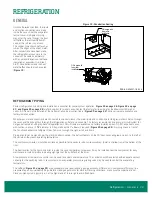
Unless otherwise specified, the liquid
and suction connections are made
inside the case under the evaporator
fan/coil cover. Refrigerant piping
may enter the case through the front
left bottom, the left rear bottom of
case, or the left rear top of case.
The copper pipe should not touch or
rub on the edges of the sheet metal.
After connections have been made,
the refrigeration access hole in the
case must be sealed completely
with an aerosol-dispensed Urethane
insulation or equivalent (i.e. Great
Stuff). Penetrations made in sheet
metal baffles should also be sealed
(
REFRIGERANT PIPING
Correct refrigeration line sizing and installation is essential for proper system operation.
,
27, and Figure 25 on page 28
are for Evolution (V) model cases. Contact the factory for line sizing for the Maximizer (M) model
cases. A P-trap must be installed at the bottom of all vertical suction risers (
). Various risers are available as a
factory installed option.
When two or more case sections are connected to one compressor, the main liquid and suction line for the group should be run through
the cases and be brought out through the refrigeration outlet of one case only. The factory recommends one riser per circuit/system for
hot gas defrost when using top back refrigeration exit. Circuit risers are available as a factory installed option. On 30" wide door cases
with suction lines over 1
3/8
" diameter, a P-trap made with 45° elbows is required (
). A piping chase in front of
the fan shroud allows the refrigerant lines to be run through the right or left end frame.
Piping should not be placed near the electric defrost heaters. The defrost heaters on the 30" door cases will grow one inch to the left of
the coil when they reach operating temperature.
The compressor should be installed as close as possible to the cases to reduce pressure drop. Install a shallow trap at the bottom of the
riser.
The best location for the liquid line drier is inside the case compartment. However, it may be installed near the compressor for easy
maintenance. Install moisture indicating sight glass at the outlet end of the drier.
A low pressure or temperature control can be used to control case temperature. The control should be selected with adequate contact
capacity for the switching load. In rack systems, an evaporator pressure-regulating valve may be used to control the evaporating
temperature.
) are approximate due to variations in gauge accuracy, differences in compressor efficiency, line
pressure drop and superheat settings. Before making adjustments for store or stocking conditions, make sure the superheat is set.
Close coupled systems typically run at the higher end of this range to avoid flood back.
Figure 19: Penetration Sealing
DWG. NO. SP-6007-1 REV. A
Fill in area with
foam after
installation
9561
9/20/2012
SHEET
SPECIFIED, ALL DIMENSIONS
(PER SP-0457)
INITIAL RELEASE
A
STANDARD
RELEASED
TOLERANCES:
CS
No. REVISION DESCRIPTION
ECN No.
PART WEIGHT:
NO MANUAL REVISIONS
CONSENT OF ZERO ZONE, INC. IS STRICTLY PROHIBITED.
(IN LBS)
CAD DRAWING
NONE
FINISH:
(PER SP-0404)
REPRODUCTION OR OTHER MEANS, WITHOUT THE WRITTEN
(PER SP-0154)
MATERIAL:
SIZE
NOT TO SCALE
Chris Standlee
SCALE:
(UNLESS OTHERWISE SPECIFIED)
REVISION
ZERO ZONE, INC.
DOCUMENT OR DISCLOSURE OF ITS CONTENTS; BY
ARE IN DECIMAL INCH
9/20/2012
A
1 OF 1
SP-6007-1
PENETRATION SEALING
SHEET:
DATE:
A
MODELED BY:
DRAWN BY:
UNLESS OTHERWISE
USA 53153
DRAWING No:
DESCRIPTION:
BY
DATE
COPYRIGHT INFORMATION
THIS DRAWING AND THE INFORMATION CONTAINED WITHIN, IS
THE SOLE PROPERTY OF ZERO ZONE, INC. ANY USE OF THIS
110 NORTH OAKRIDGE DRIVE
NORTH PRAIRIE, WISCONSIN
REVISION INFORMATION
Fill in area with
foam after
installation
Refrigeration - General • 23
Содержание RVZC30
Страница 2: ......
Страница 4: ......
Страница 36: ...ELECTRICAL LOW TEMP Figure 26 Electric Defrost 30 24 Wiring 32 Electrical Low Temp...
Страница 37: ...ELECTRICAL LOW TEMP CONT Figure 27 Hot Gas Wiring Electrical Low Temp 33...
Страница 38: ...ELECTRICAL LOW TEMP CONT Figure 28 Single Point Wiring 34 Electrical Low Temp...
Страница 39: ...ELECTRICAL LOW TEMP CONT Figure 29 Master Satellite Wiring Electrical Low Temp 35...
Страница 40: ...ELECTRICAL MEDIUM TEMP Figure 30 RVCC30 and RMCC24 Wiring Diagram 36 Electrical Medium Temp...
Страница 41: ...ELECTRICAL MEDIUM TEMP CONT Figure 31 Single Point Wiring Electrical Medium Temp 37...
Страница 42: ...ELECTRICAL MEDIUM TEMP CONT Figure 32 Master Satellite Wiring 38 Electrical Medium Temp...


