


BUMPER AND KICKPLATE
UNDER CASE RETURN AIR FLOW ASSEMBLY INSTRUCTIONS
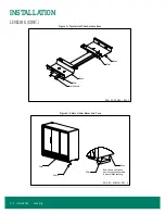
To assemble the bumper for under case return air flow (if requested), a spacer (provided) must be inserted between the bumper and
kickplate (
). The spacer is held in place with the standard black assembly screw used to attach the bumper. One
3/8
" spacer is
required at each screw location (2 spacers on a 2-door, 3 spacers on a 3-door, etc.).
1. To ease installation, hook the bumper to the case and position the kickplate. Then pull the bottom edge of the bumper forward,
hold the spacer in place, and then insert the assembly screw through the bumper, spacer, kickplate, bumper bracket and into the
Tinnerman clip.
2. With the spacers in place, air will be allowed to flow between the bumper and kickplate and then underneath the case. The target
airflow rate under the case should be 50 cfm/door.
Note: An optional louvered kickplate is available.
Figure 18: Bumper Air Flow
Bumper and Kickplate • 19
Содержание 3RMCC30WA
Страница 2: ......
Страница 4: ......
Страница 36: ...ELECTRICAL LOW TEMP Figure 26 Electric Defrost 30 24 Wiring 32 Electrical Low Temp...
Страница 37: ...ELECTRICAL LOW TEMP CONT Figure 27 Hot Gas Wiring Electrical Low Temp 33...
Страница 38: ...ELECTRICAL LOW TEMP CONT Figure 28 Single Point Wiring 34 Electrical Low Temp...
Страница 39: ...ELECTRICAL LOW TEMP CONT Figure 29 Master Satellite Wiring Electrical Low Temp 35...
Страница 40: ...ELECTRICAL MEDIUM TEMP Figure 30 RVCC30 and RMCC24 Wiring Diagram 36 Electrical Medium Temp...
Страница 41: ...ELECTRICAL MEDIUM TEMP CONT Figure 31 Single Point Wiring Electrical Medium Temp 37...
Страница 42: ...ELECTRICAL MEDIUM TEMP CONT Figure 32 Master Satellite Wiring 38 Electrical Medium Temp...


