background image

Rev A  1/7/13

ZERO ZONE

MEDIUM AND LOW TEMPERATURE 

DISPLAY CASES

INSTALLATION & OPERATION MANUAL

CASE CLOSED

Содержание 3RMCC30WA

Страница 1: ...Rev A 1 7 13 ZERO ZONE MEDIUM AND LOW TEMPERATURE DISPLAY CASES INSTALLATION OPERATION MANUAL CASE CLOSED...

Страница 2: ......

Страница 3: ...DRAIN LINE 16 BUMPER AND KICKPLATE 17 Installing End Kickplate 17 Installing Bumper 17 Under Case Return Air Flow Assembly Instructions 19 GENERAL INFORMATION 20 Cleaning 20 Shelf Location 20 Shelves...

Страница 4: ......

Страница 5: ...rovide reimbursement for such exchange as directed less any credit allowed for return of the original compressor of a compressor of like or similar design and capacity if it is shown to the satisfacti...

Страница 6: ...The end user must exercise caution and common sense when installing using or maintaining Zero Zone products If any questions or problems arise call Zero Zone at 800 247 4496 Any change to a Zero Zone...

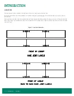
Страница 7: ...AIMS FOR DAMAGES MUST BE FILED WITH THE TRANSPORTATION COMPANY NOT WITH ZERO ZONE The carrier will supply necessary report and claim forms PACKAGING Each case in a lineup is labeled to identify the li...

Страница 8: ...gging Out of level conditions will result in reduced performance Wall cases cases set with a back to a wall and cases set back to back should be positioned to allow a minimum 2 4 space behind the back...

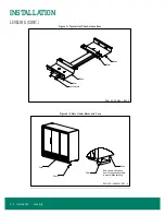
Страница 9: ...RMZC24 RVCC30 and RMCC24 2 through 5 door cases have segmented bases mounted at the ends and under the center section of the case The RVZC30 and RVCC30 1 door and RVZC30BB and RVCC30BB have full base...

Страница 10: ...Y REPRODUCTION OR OTHER MEANS WITHOUT THE WRITTEN CONSENT OF ZERO ZONE INC IS STRICTLY PROHIBITED FINISH PER SP 0154 MATERIAL PER SP 0404 UNLESS OTHERWISE SPECIFIED A SHEET SIZE NOT TO SCALE Chris Sta...

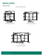
Страница 11: ...INSTALLATION LEVELING CONT Figure 5 All Base Locations A 1 Door Case B Wrap Around Case WA C 24 2 Door Case D 24 3 Door Case Installation Leveling 7...

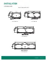
Страница 12: ...INSTALLATION LEVELING CONT Figure 5 All Base Locations Cont E 30 2 Door Back to Back Case F 30 3 Door Back to Back Case G 30 4 Door Back to Back Case 8 Installation Leveling...

Страница 13: ...INSTALLATION LEVELING CONT Figure 5 All Base Locations Cont H 30 2 Door Case I 30 3 Door Case J 30 4 Door Case K 30 5 Door Case Installation Leveling 9...

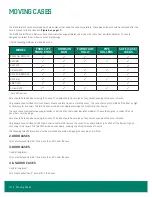
Страница 14: ...e should only be lifted off the floor as high as necessary for transport The fork truck should be driven slowly avoiding any abrupt motions or bumps The cases have steel protective support plates unde...

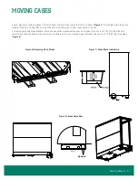
Страница 15: ...nd must be used when lifting 4 or 5 door cases with 4 bases For low shipping height applications Zero Zone has optional expandable bases As shipped the base is 1 tall It is attached with spacers that...

Страница 16: ...divider is attached to one of the cases using short bolts When the case is installed the short bolts are removed and long bolts are reinstalled to bolt both cases together Instructions for assembly o...

Страница 17: ...IN REVISION INFORMATION DWG NO SP 6005 2REV B SURFACE TEMPERATURE SHOULD BE ABOVE 40 F AND FREE OF FROST 1 Apply nonporous nonabsorbent good quality NSF approved silicon caulk sealant or Manus Bond 75...

Страница 18: ...L IS AVAILABLE 2 LABEL IS DRAWN ACTUAL SIZE 3 DWG NO SP 0397 REV H 125 4 250 5 500 RELEASED SEE NOTE SEE NOTE FINISH PER SP 0154 MATERIAL PER SP 0404 Joe Zyduck SCALE MODELED BY DRAWN BY UNLESS OTHERW...

Страница 19: ...2 1 2 INSULATED DIVIDER PANEL 3b INSTALL ONE LONGER ITEM 1 1 4 20 X 3 1 2 GRADE 8 BOLT AND ONE ITEM 3 WASHER IN THE SAME LOCATION AND ORIENTATION OF THE ORIGINAL BOLT 3c TIGHTEN TO SECURE INSULATED DI...

Страница 20: ...trap kit The drain line must be pitched away from the case The tee drain trap and plug are supplied with the case The factory installs a drain support at the front of the case on all 30 door cases We...

Страница 21: ...late INSTALLING BUMPER Figure 17 on page 18 The front kickplate and bumper attaches using 1 screws attached to brackets located on the front of the case The kickplate can be adjusted up and down to fi...

Страница 22: ...O ZONE INC DOCUMENT OR DISCLOSURE OF ITS CONTENTS BY ARE IN DECIMAL INCH 9 12 2012 B 1 OF 1 SP 6002 1 OTHER STYLE BUMPERS SHEET UNLESS OTHERWISE SPECIFIED SCALE MODELED BY DRAWN BY UNLESS OTHERWISE US...

Страница 23: ...door 3 spacers on a 3 door etc 1 To ease installation hook the bumper to the case and position the kickplate Then pull the bottom edge of the bumper forward hold the spacer in place and then insert t...

Страница 24: ...are completely seated Wire shelf brackets are stamped with R for Right and L for left to aid installation SHELVES Zero Zone manufactures many different styles of shelves baskets and product stops The...

Страница 25: ...Unless otherwise specified a superheat adjustable externally equalized thermostatic expansion valve with a removable strainer and pressure limiting charge low temp only is mounted to the evaporator c...

Страница 26: ...mb at the center of the middle door in the case other doors have slightly lower velocity A typical low temp velocity reading is 400 to 500 feet per minute in a fully packed low temp case after the cas...

Страница 27: ...ne inch to the left of the coil when they reach operating temperature The compressor should be installed as close as possible to the cases to reduce pressure drop Install a shallow trap at the bottom...

Страница 28: ...rature probes for electronic case controllers may be installed in many different customer specified locations including but not limited to honeycomb ceiling pocket cover rear wall and return air LEAK...

Страница 29: ...30 door Condensing unit cut in 27 psig Condensing unit cut out 16 psig CONDENSING UNIT VC and VCT2 30 door Condensing unit cut in 74 psig Condensing unit cut out 62 psig MZ 24 door and WA Condensing u...

Страница 30: ...00 7 8 5 290 8 780 7 8 4 230 7 030 7 8 3 610 6 000 7 8 12 810 20 300 7 8 8 790 14 000 7 8 7 040 11 200 7 8 6 010 9 530 7 8 20 310 41 000 1 1 8 14 010 28 200 1 1 8 11 210 22 700 1 1 8 9 540 19 400 1 1...

Страница 31: ...6 310 10 500 7 8 4 330 7 180 7 8 3 460 5 750 7 8 2 960 4 910 7 8 10 510 16 600 7 8 7 190 11 400 7 8 5 760 9 120 7 8 4 920 7 790 7 8 16 610 33 600 1 1 8 11 410 23 100 1 1 8 9 130 18 600 1 1 8 7 800 15...

Страница 32: ...15 910 26 300 7 8 10 910 18 100 7 8 8 750 14 600 7 8 7 480 12 500 7 8 26 310 41 600 7 8 18 110 28 700 7 8 14 610 23 100 7 8 12 510 19 700 7 8 41 610 84 000 1 1 8 28 710 58 000 1 1 8 23 110 46 700 1 1...

Страница 33: ...ocal codes After installation of the equipment correct operation of the electrical circuits and controls and defrost operation and termination should be verified All operating voltages and amperages s...

Страница 34: ...he kickplate and prewired The liquid line solenoid is prewired but is not installed in the liquid line The power to operate each display case is connected at each case s disconnect switch The power to...

Страница 35: ...here are interconnecting wires that need to be connected between the cases The liquid line solenoid valve needs to be installed in the common liquid line before the liquid is distributed to the cases...

Страница 36: ...ELECTRICAL LOW TEMP Figure 26 Electric Defrost 30 24 Wiring 32 Electrical Low Temp...

Страница 37: ...ELECTRICAL LOW TEMP CONT Figure 27 Hot Gas Wiring Electrical Low Temp 33...

Страница 38: ...ELECTRICAL LOW TEMP CONT Figure 28 Single Point Wiring 34 Electrical Low Temp...

Страница 39: ...ELECTRICAL LOW TEMP CONT Figure 29 Master Satellite Wiring Electrical Low Temp 35...

Страница 40: ...ELECTRICAL MEDIUM TEMP Figure 30 RVCC30 and RMCC24 Wiring Diagram 36 Electrical Medium Temp...

Страница 41: ...ELECTRICAL MEDIUM TEMP CONT Figure 31 Single Point Wiring Electrical Medium Temp 37...

Страница 42: ...ELECTRICAL MEDIUM TEMP CONT Figure 32 Master Satellite Wiring 38 Electrical Medium Temp...

Страница 43: ...y depending on how much frost is on the coil and the defrost heater voltage Coil frost is a function of shopping patterns stocking habits general door maintenance and ambient temperature and humidity...

Страница 44: ...r of the case and then into the evaporator Condensed liquid leaves the evaporator through the side port distributor through a check valve into the liquid line Figure 33 and Figure 34 on page 41 Genera...

Страница 45: ...10 9 11 7 13 6 5 12 4 3 2 1 14 30 HOT GAS DEFROST DWG NO SP 3000 REV E I O MANU TOLERANCES PER SP 0457 STANDARD PART WEIGHT IN LBS CAD DRAWING NO MANUAL REVISIONS COPYRIGHT INFORMATION THIS DRAWING A...

Страница 46: ...the floor on the right hand side of the coil Remove fasteners holding the heater to the floor The U shape defrost heater can be removed by first pulling the front leg of the retaining clip away from t...

Страница 47: ...EW ISSUE SPECIFIED ALL DIMENSIONS PER SP 0457 A DOCUMENT OR DISCLOSURE OF ITS CONTENTS BY PART WEIGHT STANDARD I O MANUA TOLERANCES NO MANUAL REVISIONS NONE NONE IN LBS CAD DRAWING No MATERIAL SIZE NO...

Страница 48: ...minutes If temperature termination is selected the termination temperature is set for 45 F for discharge air and coil temperature Stocking or shopping activities during defrost may result in premature...

Страница 49: ...r to Zero Zone Installation and Operation Manuals available on the Service page at WWW ZERO ZONE COM or contact the Zero Zone Service Department at 800 247 4496 All specifications subject to change wi...

Отзывы: