KNK
Logical
Interface
for
Climate
ZN1CL
–
KLIC
‐
DI
Technical
Note:
Installation
Note
© Zennio Avance y Tecnología S.L. Edition 5 For further information
www.zennio.com
Page.
2
of
5
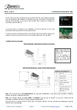
On the other hand, for connecting the device KLIC-DI to the air-conditioning internal
unit, the terminal P1/P2 located in the PCB of the AC unit must be connected to
terminal P1/P2 located in one side of the KLIC-DI (this connector is included as
accessorize with the device).
If a wired control is included in the installation, the device KLIC-DI can be also
connected to the terminal P1/P2 of the wired control.
In order to locate the terminal P1/P2 in the PCB of the wired control, remove the
casing of the wired control and look for the terminals marked as P/P1 and N/P2.
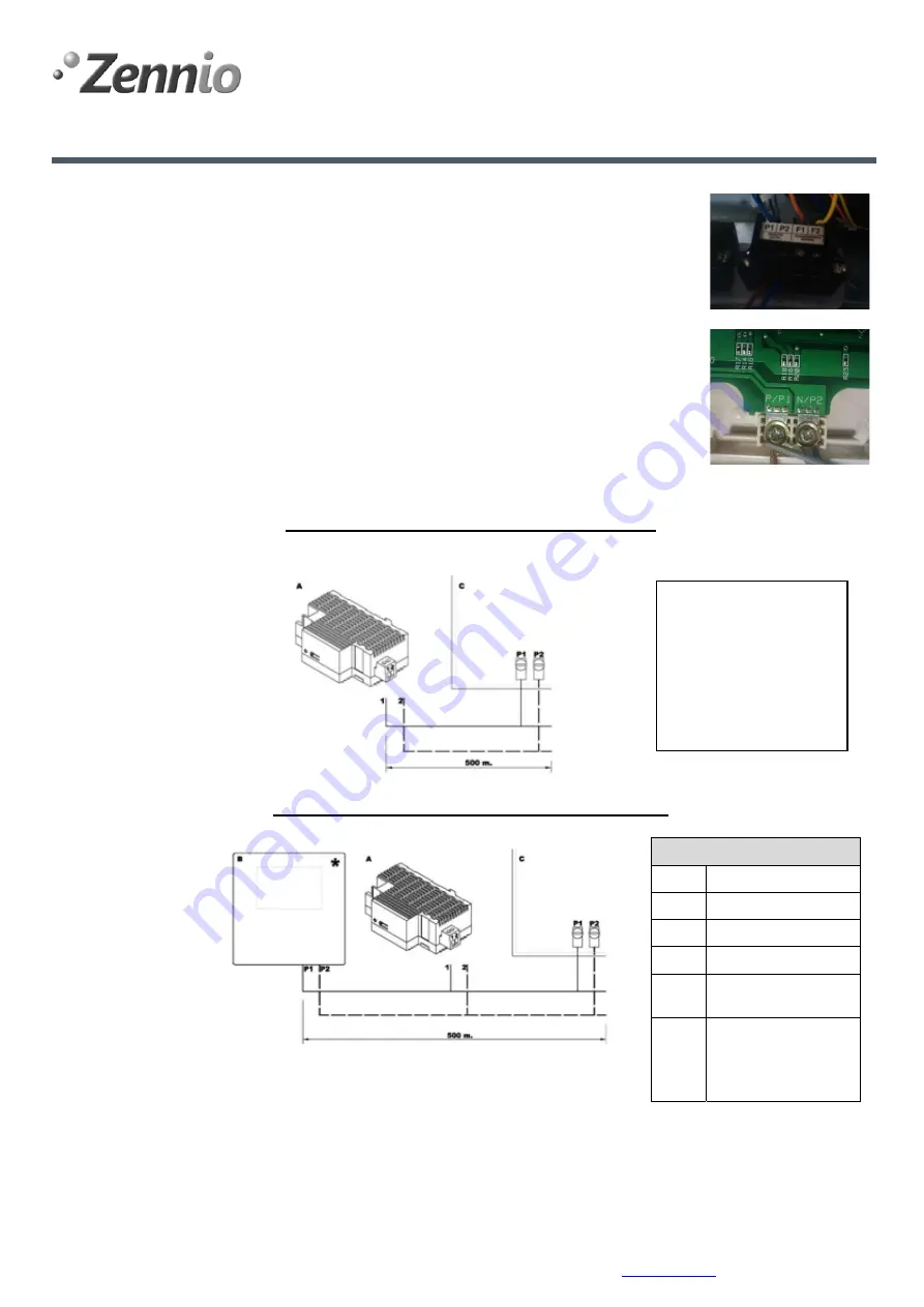
CONNECTIONS DIAGRAMS
KLIC-DI (master, without wired control in the bus):
KLIC-DI (master/slave) + wired control (slave/master):
Leyend
Connection
Diagrams
A
KLIC
–
DI
B
wired
control
C
internal
unit
P1
‐
P2
connection
bus
1
‐
2
Zennio’s
connection
terminal
*
The
wired
control
must
work
as
slave
when
KLIC
‐
DI
is
master
and
vice
versa
Note:
The wired remote controller
BRC1E51A7
can only work as MASTER. In case this remote controller is installed,
KLIC-DI should be configured as SLAVE.
Note:
The infrared remote controllers
BRC7*
and
BRC4*
can only work as SLAVE. In case any of these remote
controllers is installed, KLIC-DI should be configured as MASTER.
Once the device is powered from the KNX bus, the physical address and the corresponding application program
KLIC-DI can be downloaded.
Note
: Each KLIC-DI is
able to control
only one
internal unit.
It is not possible to
connect several internal
units in series and
control them with KLIC-
DI.


