


DALIBOX Interface 64/32
Technical Support:
23
It is important to note that this functionality may have certain consequences over ballast
replacements or group error detections. For example:
While the Standby mode remains active (i.e., while the ballast power supply
remains interrupted),
DALI-related errors
such as the ballast presence error
or the diagnostic errors will no longer be detected.
During
ballast initialisation
or DALI address assignment, any attempts to
activate the Standby mode will be postponed by 30 seconds, as many times as
necessary until such process is finished.
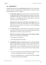
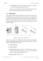
The following example illustrates how the Standby mode works:
Figure 8.
Standby mode action sequence
Important
:
Ballasts with no group assignment (see section 2.22.2) should not to be
connected to the actuator that interrupts the power supply, as they may cause
a ballast presence error notification when the Standby mode gets activated.
Standby mode and emergency ballast are compatible, but this type of ballast
should not be switched off as it would go into emergency mode and drain the
battery.
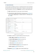
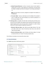
ETS PARAMETERISATION
Once the
Standby
function is enabled from the General Functions section, in the
“General” parameter tab (see section 2.1), the following parameter becomes available:
Status: 50%
Status: 0%
Dimming: 0%
Standby = 1
Dimming: 50%
Error Detect.
X
Error Detect.
√
Standby = 0
Status: 50%


